
Short answer
Axial piston motor displacement is calculated from the flow available to the motor and the required shaft speed, then checked against torque, differential pressure, efficiency, duty cycle and the exact model limits. For a first estimate, use displacement (cm³/rev) = flow (L/min) × 1000 × volumetric efficiency ÷ speed (rpm). This gives a starting value, not a purchase specification. The final displacement must be confirmed against the motor's continuous and intermittent duty, oil temperature, control range, shaft load, mounting and current supplier data.
What Axial Piston Motor Displacement Actually Means
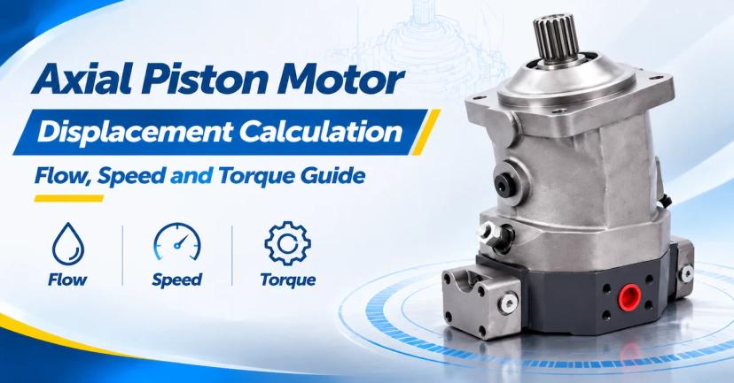
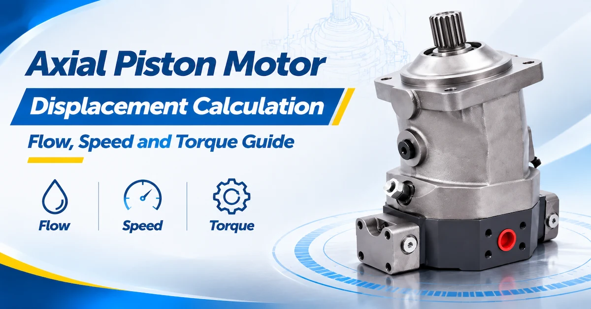
In an axial piston motor, displacement is the theoretical volume of hydraulic fluid associated with one shaft revolution. It is normally stated in cubic centimetres per revolution, written as cm³/rev or cc/rev. A larger displacement generally produces more theoretical torque at the same pressure, but it also needs more flow to reach the same speed. A smaller displacement can run faster with the same flow, while producing less torque at the same pressure.
That relationship is why axial piston motor displacement calculation should begin with the machine operating point rather than a catalogue size. An excavator travel drive, winch, mixer, drilling attachment and closed-loop wheel drive may use the same motor family while requiring different displacement because their flow, speed, torque, gearbox ratio and duty cycle are different. The number that looks correct in a search result may be wrong once efficiency, pressure drop, control range or external load is included.
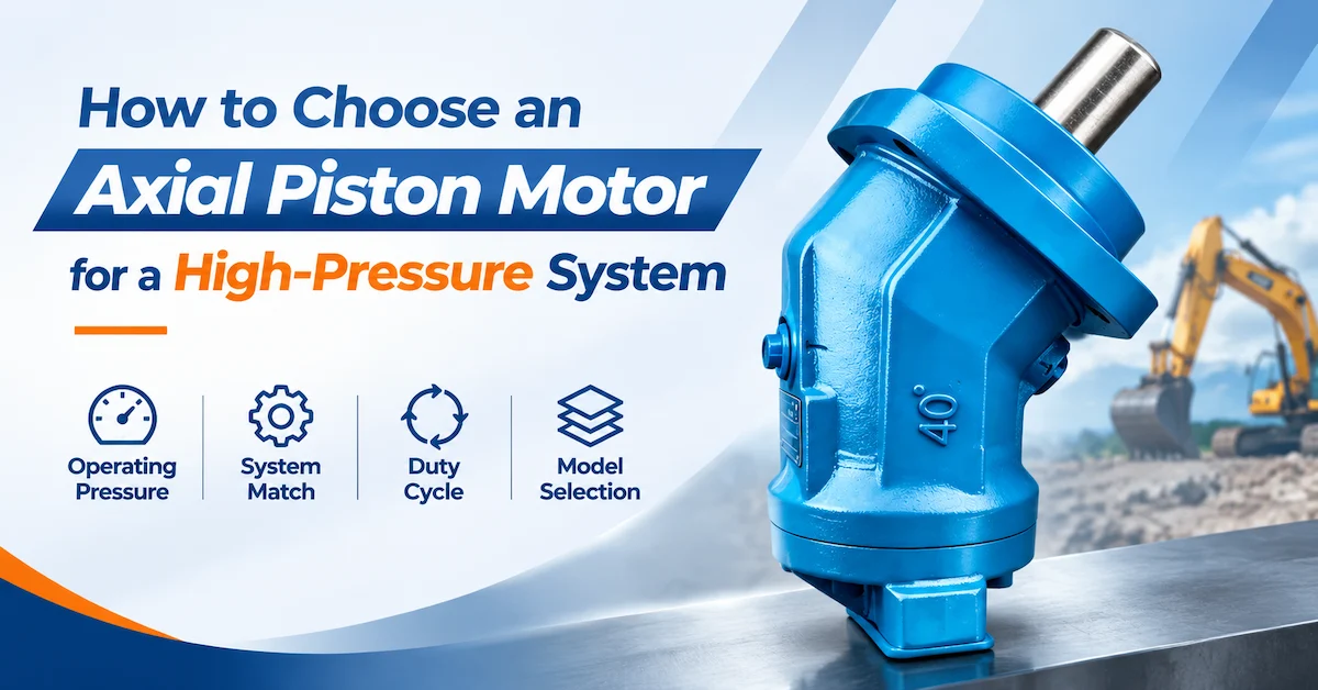
BLINCE provides a dedicated hydraulic axial piston motor category for reviewing available motor families. The A2FE Series page describes a fixed-displacement bent-axis plug-in motor and lists family sizes from 28 to 355 cm³/r. The A2FM Series page describes a fixed-displacement bent-axis motor for hydrostatic drives and lists sizes from 10 through 180. These ranges are useful for screening; they are not the rating of every individual model.
The Three Calculations You Need Before Choosing a Size
A useful calculation separates speed, torque and power. They describe different parts of the same operating point. Speed is mainly linked to flow and displacement. Torque is mainly linked to differential pressure and displacement. Hydraulic power is linked to pressure and flow. A motor can satisfy one of these checks and fail another, so do not select a displacement from speed alone.
1. Displacement from flow and speed
Vg = required displacement; Q = motor flow; ηv = volumetric efficiency used for the estimate; n = required shaft speed.
The ideal equation without efficiency is Q × 1000 ÷ n. Adding volumetric efficiency makes the estimate more realistic because leakage means the motor may need more theoretical flow than the ideal calculation suggests. Use an efficiency assumption only for preliminary sizing. The supplier must replace the assumption with model-specific data at the pressure, speed, viscosity and temperature in your machine.
2. Torque from pressure and displacement
Δp = pressure drop across the motor; ηm = mechanical efficiency used for the estimate.
Use the pressure difference across the motor, not automatically the pump relief setting. Inlet pressure, outlet pressure, valve losses, return back pressure and overrunning loads can change the actual Δp. Mechanical efficiency accounts for friction and other losses. Starting torque, continuous torque, intermittent torque and peak torque should be listed separately because each may have a different allowable duration.
3. Hydraulic power from pressure and flow
The shaft power is lower after mechanical and volumetric losses.
Power is a useful cross-check. If your calculated motor displacement requires a flow and pressure combination that exceeds the pump, cooler, valve or engine capacity, the displacement is not a complete solution. Conversely, a small motor forced to produce the required torque near relief pressure can generate excessive heat and have little reserve for acceleration.
A Worked Axial Piston Motor Displacement Calculation
Consider a closed-circuit construction attachment that must run at 240 rpm. The motor receives 72 L/min at the normal operating point. For a first estimate, assume volumetric efficiency of 0.92. The displacement calculation is:
A nominal motor near 276 cm³/rev becomes the initial search area. It does not mean that a 280 cm³/rev motor is automatically correct. The engineer must check whether the selected family contains that displacement, whether the exact model can run at 240 rpm under the pressure condition, and whether the machine's maximum flow would overspeed the motor. If a standard size is 250 cm³/rev, the team should calculate the actual speed at 72 L/min and then verify torque and thermal behavior. If a standard size is 315 cm³/rev, the team should check whether the available flow can achieve the required speed and whether the larger motor changes gearbox torque or control response.
Now assume the normal differential pressure is 280 bar and the preliminary mechanical efficiency is 0.90. The theoretical torque estimate for 276 cm³/rev is:
This is a screening result. It is not a guaranteed continuous torque value. The supplier must confirm continuous and intermittent torque for the exact model, including speed, pressure duration, oil temperature, allowable case pressure and any external radial or axial load. The calculation is valuable because it exposes the expected load and gives the supplier enough information to return a meaningful model recommendation.
Calculate the Full Flow Range, Not Only the Normal Point
Many sizing errors occur because a buyer calculates displacement at one flow and ignores the machine's minimum and maximum flow. A pump may operate at low flow during fine positioning, share flow with another actuator, or deliver a higher flow during a fast travel command. Calculate at least three points: minimum flow, normal flow and maximum flow.
| Operating point | What to calculate | Why it matters | Evidence to request |
|---|---|---|---|
| Minimum flow | Actual rpm after volumetric leakage and control losses | Low-speed smoothness, stall margin and controllability | Minimum stable speed and low-flow test condition for the exact model |
| Normal flow | Speed, torque and power at the main production point | Primary sizing and thermal duty | Continuous rating, efficiency assumptions and cooling requirements |
| Maximum flow | Maximum rpm and hydraulic power | Overspeed, noise, bearing stress and temperature | Maximum speed at the stated pressure, displacement and oil temperature |
| Shared flow | Flow left for the motor when other actuators operate | Speed drop and unstable machine behavior | Control logic, flow-sharing assumptions and minimum useful speed |
For example, if a 250 cm³/rev motor receives 50 L/min, the ideal speed is 200 rpm before volumetric losses. At 75 L/min, the same motor is theoretically at 300 rpm. That range may be suitable for one machine and too wide for another. If the motor is part of a variable-displacement transmission, the control system may reduce displacement to increase speed; the calculation must then use the minimum and maximum displacement settings, not one nominal value.
Efficiency: Use It to Size, Then Verify It
Efficiency is not one universal constant. Volumetric efficiency changes with pressure, speed, viscosity, temperature, clearances and wear. Mechanical efficiency changes with friction, load, lubrication and speed. Total efficiency combines these effects, but a catalogue may show theoretical, typical or maximum values under different test conditions.
For preliminary axial piston motor displacement calculation, use a conservative engineering assumption and show it in the worksheet. Do not hide the assumption inside a rounded displacement. Ask the supplier to return the expected speed, torque and power at the exact duty point, including the efficiency basis. If the supplier cannot provide a model-specific curve, keep the result as a shortlist rather than a released design value.
Temperature matters because hot oil is thinner and leakage can increase. A motor may deliver the expected speed on a cold test bench but lose speed or generate more heat after the machine reaches operating temperature. State ambient temperature, oil temperature, viscosity range, filtration and cooler arrangement in the RFQ. For a repair replacement, record the old unit's oil condition and failure evidence before assuming that a new motor will restore performance.
Fixed and Variable Displacement Calculation Paths
For a fixed-displacement motor, one nominal Vg is used in the speed and torque calculations. The pump or valve controls flow, while the motor converts that flow into shaft speed and pressure into torque. The BLINCE A2FE Series is described as a fixed-displacement bent-axis plug-in motor with family sizes from 28 to 355 cm³/r. Its published family information also identifies nominal pressure up to 40 MPa and peak pressure up to 45 MPa. These values must be matched to the exact displacement, shaft type, radial-load condition and duty definition.
The BLINCE A2FM Series is described as a fixed-displacement bent-axis unit for hydrostatic drives in open and closed circuits. The page lists size-dependent displacement, speed, power and torque information. A buyer can use the listed size range to create a shortlist, but should not treat the smallest or largest published value as the rating of every A2FM model.
For a variable-displacement motor, calculate at both minimum and maximum displacement. At minimum displacement, the same flow can create much higher speed. At maximum displacement, the motor can produce more torque at a given pressure but may require more flow. The control method, response, minimum setting, maximum setting and fail-safe position become part of the calculation. BLINCE's A6VM product page can be used as a variable-displacement review entrance, but the current model-specific data must be requested before approval.
Pressure Drop Is the Input to Torque, Not Relief Setting Alone
Torque is produced by differential pressure across the motor. A pump relief setting tells you how the circuit is protected, but it does not tell you the pressure drop available at the motor during every condition. Pressure can be lost across valves, hoses, filters and other actuators. In a closed circuit, charge pressure, loop relief and overrunning loads can change both motor ports. In an open circuit, return back pressure can affect sealing and housing stress.
Separate these values in the worksheet:
- Pump outlet or supply pressure.
- Motor inlet pressure.
- Motor outlet or return pressure.
- Differential pressure across the motor.
- Case or drain pressure.
- Relief setting and the duration of any relief event.
Then calculate torque at the normal, intermittent and peak differential pressure. A motor that meets a short peak torque calculation may not be suitable for continuous work at the same pressure. The supplier should identify whether each quoted torque is theoretical, measured, continuous, intermittent or peak, and state the applicable speed and oil conditions.
Mechanical Checks That Can Change the Calculated Size
A hydraulic calculation does not account for every mechanical constraint. Gearbox ratio, wheel radius, drum diameter, chain pitch, screw lead and driven inertia can change the torque and speed required at the motor shaft. Calculate the load at the motor after the transmission ratio, then include acceleration torque, friction and shock. A larger displacement may reduce the pressure required for steady torque, but it can increase the torque delivered to a gearbox during a jam.
Check shaft, spline, flange, pilot, radial load and axial load at the same time as displacement. The motor may be hydraulically capable but mechanically unsuitable. For a direct gearbox or plug-in installation, compare the controlled drawing rather than relying on a product photograph. For a repair, record the old motor code, shaft end, ports, mounting face, rotation and any adapter before asking for a quote.
| Mechanical input | Question to answer | Why it affects calculation or approval |
|---|---|---|
| Gear ratio | What motor rpm produces the required output rpm? | Changes the flow and displacement required at the motor |
| Driven inertia | What torque is needed for acceleration and stopping? | May make intermittent torque more important than steady torque |
| Radial load | Does a chain, belt, sprocket or wheel load the shaft? | Determines shaft and bearing suitability for the exact model |
| Axial load | Does the driven assembly push or pull along the shaft? | Can require separate support bearings or a different configuration |
| Mounting envelope | Will the selected displacement fit the frame, hoses and gearbox? | A larger body or port orientation may require redesign |
Thermal and Circuit Checks After the Formula
Once displacement, speed and torque look correct, check heat. Losses appear as pressure drop, leakage, friction, valve throttling and flow through cooling or flushing circuits. Estimate the hydraulic input power, subtract useful shaft power and confirm that the reservoir, cooler and housing can reject the remaining heat. If the motor spends a large percentage of time near relief pressure, the continuous thermal point may control the selection even when the peak torque requirement is higher.
For a closed hydrostatic loop, include charge pressure, flushing flow, loop relief, cross-port relief, anti-cavitation protection and the behavior during neutral, acceleration, braking and reversal. For an open circuit, include pump type, valve arrangement, return back pressure, drain routing and reservoir capacity. The same displacement can behave differently in the two circuits because pressure, flow and cooling paths are different.
Oil cleanliness and viscosity should be written into the RFQ. A calculation based on clean, cool oil cannot be treated as proof for a dusty mobile machine with a hot reservoir and a restricted filter. Ask the supplier for commissioning requirements, filtration guidance and the conditions used for any published efficiency or speed data.
What to Send in an RFQ for a Displacement Recommendation
A supplier can give a useful recommendation when the calculation inputs are visible. Send the worksheet, hydraulic schematic, machine drawing and old-unit evidence if applicable. Ask the supplier to return the exact model, a technically acceptable alternative, the assumptions and the data that still requires engineering confirmation.
| RFQ section | Information to provide | Supplier response requested |
|---|---|---|
| Required output | Motor rpm, output torque, gearbox ratio, acceleration and stopping conditions | Recommended displacement and calculated operating points |
| Hydraulic supply | Minimum, normal and maximum flow; inlet pressure; return pressure; differential pressure | Speed, torque, power and pressure limits for the exact model |
| Efficiency basis | Oil type, viscosity, temperature, filtration and cooling | Volumetric/mechanical efficiency assumptions and thermal conditions |
| Duty cycle | Continuous hours, intermittent duration, starts, reversals, stalls and overrunning loads | Continuous, intermittent and peak suitability |
| Interface | Flange, pilot, shaft/spline, ports, rotation, drain and external loads | Controlled drawing, configuration code and compatibility statement |
| Validation | Sample quantity, test equipment, acceptance limits and required documents | Sample plan, test method, traceability and quotation assumptions |
Do not ask for a quotation using only “80 cc” or “100 cc.” State whether that number is a target nominal displacement, a replacement reference or a result from a preliminary calculation. This prevents the supplier from quoting a visually similar motor with a different shaft, control, pressure category or duty assumption.
Common Displacement Calculation Mistakes
Using pump flow instead of motor flow
A pump may supply several functions, lose flow through valves or share flow with another motor. Use the flow actually available at the motor ports for each operating point.
Ignoring volumetric efficiency
The ideal flow equation can understate the displacement needed at pressure and temperature. Use an explicit preliminary efficiency assumption, then ask the supplier to verify the actual value.
Using relief pressure as motor differential pressure
Pressure losses and return pressure change Δp. Calculate torque using the pressure drop across the motor and separate normal, intermittent and peak conditions.
Selecting from one speed point
Check minimum, normal, maximum and shared-flow conditions. A motor can meet the normal speed while overspeeding at maximum flow or becoming unstable at low flow.
Treating family ranges as a single model rating
A2FE and A2FM ranges are useful product entrances, but every displacement and configuration has its own limits. The current model datasheet and engineering confirmation control the purchase decision.
Forgetting the gearbox and external load
Gear ratio, inertia, radial load and axial load can change the required torque and the acceptable shaft configuration. Include them before approving the displacement.
FAQ: Axial Piston Motor Displacement Calculation
What is the basic axial piston motor displacement calculation?
For a first estimate, use Vg (cm³/rev) = flow (L/min) × 1000 × volumetric efficiency ÷ speed (rpm). Then verify torque from differential pressure, power, duty cycle, temperature, interfaces and the exact model limits.
How do I calculate displacement if efficiency is unknown?
Calculate an ideal value first, show the assumption clearly and use a conservative preliminary efficiency for the shortlist. Ask the supplier to replace that assumption with model-specific data at the actual pressure, speed, viscosity and temperature.
Does a larger displacement always produce more torque?
A larger displacement generally produces more theoretical torque at the same differential pressure, but actual torque depends on mechanical efficiency, pressure drop, speed, temperature and duty. A larger motor also needs more flow to reach the same speed.
What is the difference between nominal and variable displacement?
A fixed motor uses one nominal displacement, while a variable motor changes displacement within a controlled range. Variable-motor calculations must check minimum and maximum settings because the same flow can produce very different speeds and torque levels.
Can I use the A2FE or A2FM family range as the final calculation input?
No. The family range helps identify a product path. Use the exact model, displacement, pressure category, speed limit, shaft, mounting, efficiency and duty conditions from the current controlled data sheet and written engineering confirmation.
Why does low flow matter in a motor calculation?
Low flow can reduce speed and leave less margin for leakage, friction and control stability. Check the minimum useful speed and the supplier's low-speed behavior at the actual oil temperature and load.
What pressure should be used in the torque equation?
Use differential pressure across the motor, not automatically the pump relief setting. Record inlet pressure, outlet pressure, return back pressure, valve losses and any transient or overrunning condition.
What should I send to BLINCE for a model recommendation?
Send flow and speed at minimum, normal and maximum points; continuous and peak torque; differential pressure; duty cycle; oil and temperature; circuit schematic; shaft, flange and port dimensions; external loads; and the old-unit code or photographs if it is a replacement. Use the BLINCE contact page to request the model-specific review.
Conclusion
Axial piston motor displacement calculation is the beginning of selection, not the end. Calculate displacement from actual motor flow and required speed, check torque at differential pressure, cross-check hydraulic power, and repeat the calculation at minimum, normal and maximum flow. Then include efficiency, temperature, duty cycle, circuit protection, gearbox ratio, shaft loads and installation dimensions.
For construction OEMs, hydrostatic system integrators and hydraulic repair buyers, the BLINCE axial piston motor category provides a starting point for fixed and variable motor families. Before releasing a purchase order, send the calculation worksheet and machine data to engineering and request written confirmation of the exact displacement, pressure, flow, speed, torque, interfaces and compatibility.