
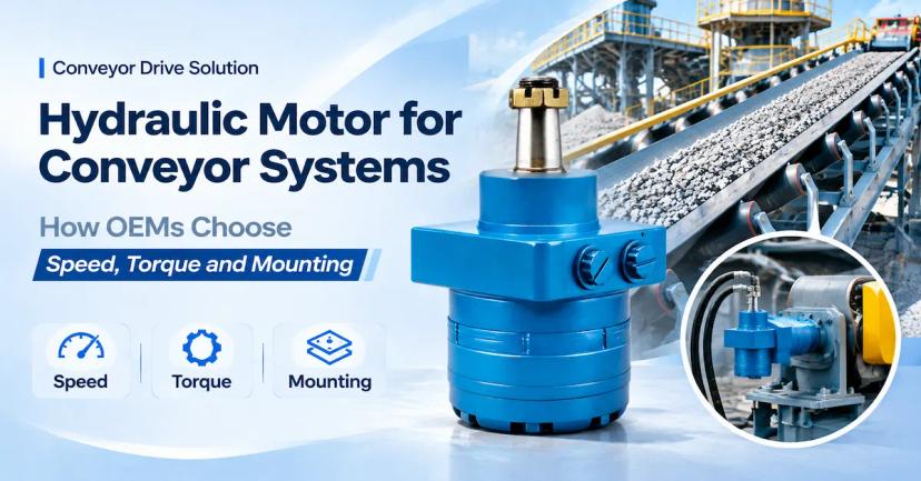
Hydraulic Motor for Conveyor Selection: What Must Be Confirmed?
A suitable hydraulic motor for conveyor is selected from the conveyor's real torque, speed, starting, stopping and installation requirements. It is not selected by motor size alone or by copying the highest number shown for a product family. The buyer needs a model that can deliver the required drum or sprocket torque at the pressure drop available in the circuit, run at the required speed with available flow, survive start-under-load and transient loads, and fit the shaft, flange, ports and reducer without an unplanned adapter.
For a belt, roller, screw or feeder conveyor, begin with the driven load. Define belt speed, drum diameter, material mass, incline, friction, acceleration time, jam risk and hours per shift. Then calculate a preliminary output torque and speed, select a displacement range, and check the candidate against the current model-specific drawing and rating sheet. BLINCE's hydraulic orbital motor range can be a practical starting point for compact and medium conveyor drives, while heavier or high-power installations may require an axial-piston solution such as the A2FE series. The final choice must be confirmed for the exact model and duty.
The most useful supplier response is a model-specific proposal that lists continuous and intermittent pressure, flow, speed, torque, starting capability, shaft load, port standard, mounting dimensions, oil and temperature assumptions, test evidence and any open compatibility questions. That level of detail lets an OEM, system integrator or repair buyer compare technical risk and total procurement cost, not just catalogue price.
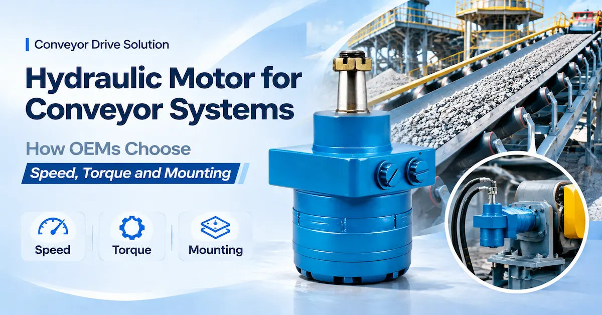
Review BLINCE Conveyor Motor Options
Conveyor Type Changes the Motor Requirement
The phrase “conveyor drive” covers several different mechanical loads. A motor that works well on a lightly loaded roller conveyor may not provide the starting torque or shock tolerance needed by an inclined belt conveyor. Describe the conveyor mechanism before asking for a motor recommendation.
Belt conveyors
A belt conveyor usually transmits motor torque through a drive drum, gearbox, chain or direct coupling. The motor must overcome belt tension, material weight, incline, skirt friction, idler resistance and acceleration. Start-up can be the governing condition when the belt is loaded or material has settled against a stop. A lagged drum increases available traction but also changes the torque and speed calculation because the effective diameter can vary with belt thickness and wear. Ask the supplier to review the actual drum diameter, reducer ratio, belt tension and external radial load at the shaft.
Roller conveyors
Powered roller conveyors may use a chain drive, line shaft, individual roller motors or a geared drive. The load changes as packages accumulate, transfer between zones or stop against a sensor. Smooth low-speed operation and controllable acceleration can matter more than peak speed. Check whether the motor drives one roller or a group, how torque is shared, and whether the chain pull or sprocket load is carried by the motor shaft or by a separate bearing. If the motor sees a large overhung load, a standard configuration may not be suitable without written confirmation.
Screw conveyors
A screw conveyor can develop high starting torque when material compacts in the trough, when moisture changes the bulk density or when the screw reverses to clear a plug. Flight geometry, pitch, fill level and product friction determine the load. The motor often connects through a reducer, coupling and thrust-bearing arrangement. Confirm whether axial thrust is reacted by the gearbox or by the motor assembly, because an orbital motor shaft should not be assumed to carry an external thrust load that the product drawing does not allow.
Feeders and apron conveyors
Apron feeders, vibrating feeders and heavy-duty belt feeders can see impact loading, frequent starts and a high breakaway torque. A feeder may also be required to reverse briefly during a blockage. These conditions can move the selection beyond a small orbital motor, even when the average running speed is low. Consider a higher-pressure orbital family only when its exact model limits and shaft-load capability fit the design; for high power, high pressure or severe transients, escalate the RFQ to an axial or radial piston motor review.
| Conveyor type | Load that often governs | Information to send with the RFQ |
|---|---|---|
| Belt conveyor | Loaded start, incline, belt tension, drum traction and shock | Belt speed, drum diameter, reducer ratio, material mass, duty cycle and shaft loads |
| Roller conveyor | Accumulation, acceleration, chain pull and package transfer | Roller count, load per zone, drive arrangement, sprocket data and stopping frequency |
| Screw conveyor | Breakaway torque, plug clearing, product friction and axial thrust | Screw diameter, pitch, fill, bulk density, reducer, thrust bearing and reverse cycle |
| Feeder/apron | Impact, repeated starts, jam recovery and high breakaway load | Peak load, start frequency, shock description, speed range and pressure transients |
Calculate Conveyor Speed and Torque Before Comparing Motors
A preliminary calculation prevents a common buying error: choosing a motor because its nominal displacement looks close to an old unit while ignoring the drum, reducer and actual load. Use the following relationships as screening tools. They are engineering estimates; the selected model, efficiency, pressure limits, temperature range and external loads require confirmation from the supplier's current technical documents.
Drum speed from belt speed
For a belt speed v in metres per second and an effective drum diameter D in metres, the drum speed is approximately ndrum = 60 × v ÷ (π × D). A smaller drum needs more revolutions per minute for the same belt speed. Include belt thickness, lagging and any working-diameter change in the value of D. If the conveyor uses a gearbox with a motor-to-drum speed ratio i, the preliminary motor speed is nmotor = ndrum × i.
Drum torque from tangential force
If the required tangential force at the drum is Ft in newtons, the drum torque is approximately Tdrum = Ft × D ÷ 2. The force should include steady resistance, incline, acceleration and a defined allowance for starting or shock. Do not hide a jam load inside an unexplained service factor. State whether it is a short-duration event, a repeated event or a condition the control system should prevent.
Motor torque after the reducer
With a reducer ratio i and gearbox efficiency ηg, a first estimate is Tmotor ≈ Tdrum ÷ (i × ηg). Confirm how the ratio is defined because some drawings quote motor speed divided by output speed while others use the inverse. Include coupling, chain and bearing losses where they materially affect the load. A supplier should return the assumed ratio and efficiency instead of silently applying a generic value.
Flow from displacement and speed
For displacement Vg in cm3/rev and motor speed n in rpm, a preliminary hydraulic flow is Q ≈ n × Vg ÷ (1000 × ηv), where ηv is volumetric efficiency. The real flow also depends on leakage, oil viscosity, temperature and pressure. Use the equation to compare the requested speed with the pump and valve capacity, then ask for the exact model's flow limit and performance at the operating temperature.
| Input | Why it matters | Validation question |
|---|---|---|
| Belt speed and drum diameter | Sets output speed and therefore motor speed after gearing | Are diameter, lagging and reducer ratio measured or assumed? |
| Tangential force and incline | Sets drum torque for steady and accelerating operation | Does the force include loaded start and transient resistance? |
| Pressure drop | Determines available hydraulic torque | Is it motor pressure drop or system relief pressure? |
| Flow and displacement | Determines speed range and heat generation | Are continuous, peak and minimum stable speeds stated? |
Send these calculations with the RFQ. When the supplier sees the load path, it can identify whether a compact orbital motor is appropriate or whether the conveyor should be reviewed with a different motor architecture. The calculation also gives both sides a common language for discussing torque margin, flow margin and temperature rather than relying on an isolated maximum value.
Check the OMP Series for Conveyor Duty
Choose the Motor Architecture Around the Duty
Orbital, axial-piston and radial-piston motors can all appear in conveyor specifications, but they solve different combinations of speed, torque, pressure, size and control. The correct question is not “Which technology is best?” It is “Which architecture provides the required output at the available flow and pressure while meeting the installation and transient-load limits?”
Orbital motors for compact and medium conveyor drives
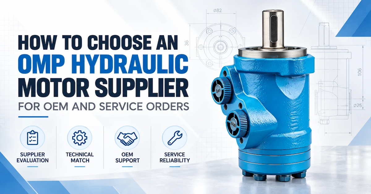
Orbital motors are often considered where a compact package, smooth low-speed motion and straightforward hydraulic control are valuable. The BLINCE OMP family page presents a family-level displacement range of 36–500 cm3/rev, speed indications up to 1500–1650 rpm, flow up to 60 L/min and torque up to 400+ Nm. These are screening references for the family, not a rating for every displacement or shaft option. For a conveyor, confirm the exact model's continuous and intermittent torque, pressure drop, speed, flow, starting behaviour, shaft load, port arrangement and temperature limits.
The OMPH family is another orbital path presented by BLINCE with family-level displacement guidance of 36–500 cm3/rev, speed up to 1500–1650 rpm, flow up to 60–75 L/min, torque up to 486 Nm and pressure indications above 20 MPa. The higher family-level figures do not automatically make OMPH suitable for a loaded feeder or jammed screw. Request the current drawing and model data, and make sure the quoted pressure is defined as continuous, intermittent or peak and tied to a duration and temperature.
OMR and OMRS when interface and starting behaviour dominate
The BLINCE OMR/OMRS page identifies a 36–375 family range, speed indications up to 1085 rpm and continuous torque indications up to 345 Nm, with shaft options including 25 mm or 25.4 mm keyed shafts, SAE 6B spline and tapered shaft. The page also lists G1/2 and 7/8-14 UNF port options and manifold installation. Those details can be useful when a conveyor replacement is constrained by an existing shaft or valve block. The exact port, seal, displacement and external-load capability still need confirmation for the proposed variant.
Axial-piston motors for higher power or closed-loop duty
An axial-piston motor may be more appropriate when the conveyor requires high power density, high pressure, a broad speed range, closed-loop control or direct gearbox integration. BLINCE describes the A2FE as a fixed-displacement bent-axis axial-piston motor with sizes from 28 to 355 cm3/rev, nominal pressure of 40 MPa and peak pressure of 45 MPa at the family level, with plug-in flange and spline options. Heavy conveyor applications should be reviewed against the exact size, displacement, case-drain requirement, gearbox interface, cooling arrangement and duty cycle rather than selected from the family range alone.
Radial-piston escalation for very high torque at low speed
Radial-piston motors can be considered when the conveyor or feeder needs very high starting torque at low output speed, particularly where a large gearbox would create packaging or efficiency problems. The procurement team should provide peak torque, shock duration, shaft and flange loads, brake requirements and operating hours. A product-family page or category range is a starting point; the supplier's engineering team must validate the exact LD, ZGM or other candidate configuration and its pressure, speed and mechanical limits.
| Architecture | Typical reason to review it | Do not approve without |
|---|---|---|
| Orbital | Compact package, low-speed smoothness and moderate conveyor power | Exact displacement, pressure-flow map, starting torque and shaft-load check |
| Axial piston | High pressure, high power, closed-loop control or gearbox integration | Exact size, case drain, cooling, control circuit and interface confirmation |
| Radial piston | Very high low-speed torque, severe start or shock duty | Peak torque duration, bearing loads, brake/reversal requirements and test plan |
Check the Reducer, Sprocket, Drum and Shaft Load
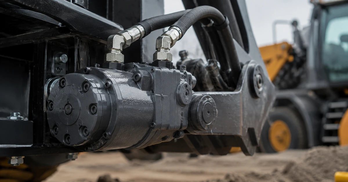
A hydraulic calculation can be correct while the mechanical installation fails. Conveyor motors commonly drive a drum, sprocket, chain, coupling or gearbox input. Each creates radial, axial or overhung loads. Record the force, direction, distance from the mounting face, shock factor and support arrangement. If a separate pillow block or gearbox bearing carries the load, show that in the drawing. If the motor shaft carries it, obtain written allowable-load data for the exact configuration.
Confirm shaft diameter, exposed length, keyway or spline, retaining thread, rotation and seal orientation. Check the pilot and bolt circle against the gearbox or bracket, not only against a photograph. Verify port size and orientation so the hoses do not impose a bending load or restrict access to the drain and relief components. A supplier should identify whether a proposed OMP, OMR/OMRS or OMPH option is direct-fit, requires an adapter, or needs a different shaft or flange variant.
Three mechanical questions that should be answered in the quotation
- Which exact shaft and flange code is included, and does the drawing match the conveyor's pilot, bolt circle and available envelope?
- What radial and axial loads are permitted at the stated distance from the mounting face, and which bearing supports the external load?
- Does the motor require a case drain, special seal, support bearing, brake or anti-cavitation protection under the proposed circuit?
Open, Closed, Series or Parallel Circuit?
Conveyor drives may use an open-circuit pump and directional valve, a closed-loop pump, or a shared series/parallel arrangement with other motors. The circuit determines how pressure, return flow, flushing, make-up oil and motor control behave. Tell the supplier whether the motor will start from a stopped loaded belt, whether it must reverse, how the motor is stopped, and whether another actuator can pressurize the return line.
In an open circuit, check relief settings, return pressure, valve pressure loss, anti-cavitation protection and the flow available during acceleration. In a closed loop, check charge pressure, flushing flow, cross-port relief, loop pressure, motor case drain and control response. In a series circuit, the pressure at each motor and the accumulated return pressure must be reviewed. In a parallel circuit, flow sharing and load differences can cause one conveyor section to run faster or stall first. Do not assume that a motor described as suitable for series or parallel use is automatically correct for every circuit; confirm the arrangement and pressure limits for the selected model.
| Circuit detail | Conveyor risk | Evidence to request |
|---|---|---|
| Return or case pressure | Seal damage, leakage or unstable starting | Maximum permitted pressure and drain arrangement for exact model |
| Reversal and stopping | Pressure spikes, belt rollback or screw plug shock | Cross-port relief, braking, ramp and anti-cavitation design review |
| Series/parallel use | Uneven speed or pressure accumulation | Circuit diagram and motor-specific series/parallel limits |
| Thermal duty | Oil overheating during long loaded runs | Oil temperature, ambient temperature, cooler capacity and test duration |
Pressure, Flow and Temperature Must Be Tied to Time
A conveyor motor can tolerate a short pressure peak that would be unacceptable as a continuous operating point. Record the pressure and flow profile over time: start, acceleration, steady running, incline changes, stop, reverse and jam recovery. Note the duration and frequency of each event. Ask the supplier to label values as continuous, intermittent or peak and to state the associated speed, oil temperature and pressure drop.
Flow affects speed and heat. Excess flow can overspeed a motor or create avoidable valve and hose losses. Too little flow can produce unstable low-speed motion, especially when friction changes or the belt is lightly loaded. Pressure drop creates torque, but pressure at the pump outlet is not the same as pressure drop across the motor. Measure or calculate both sides of the motor and include line, valve and filter losses.
Temperature changes viscosity, leakage and seal behaviour. A conveyor running continuously in a dusty plant, hot aggregate yard or washdown area needs a realistic oil and ambient temperature range. Confirm filtration, breather condition, cooler capacity, hose routing and contamination controls. The supplier can recommend a seal or installation option only when the oil, temperature and environment are described accurately.
Build a Conveyor-Specific RFQ
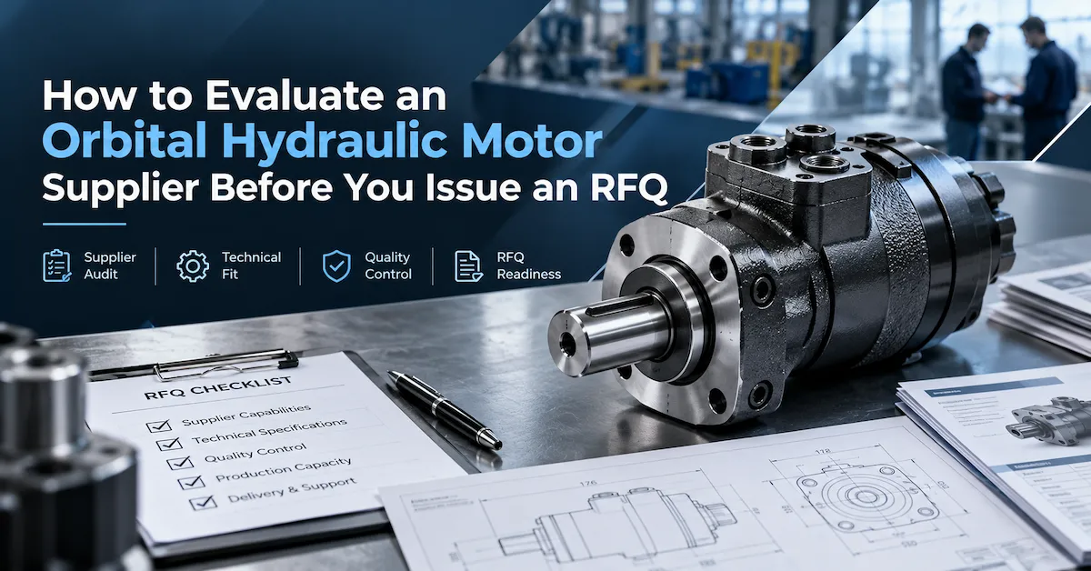
A complete RFQ saves time because the supplier can answer the technical question once instead of exchanging partial emails. Attach the conveyor layout, hydraulic schematic, old motor photographs, measured dimensions, load calculation and expected annual quantity. Separate values that are measured from values that are estimated. If the conveyor is new, include the intended reducer, drum or screw shaft and the control sequence.
| RFQ section | Buyer should provide | Supplier should return |
|---|---|---|
| Driven equipment | Belt, roller, screw, feeder or apron type; layout and material | Recommended architecture and assumptions |
| Operating point | Speed, torque, pressure drop, flow, start load, duty hours and transients | Exact model limits, calculated margin and test conditions |
| Mechanical interface | Shaft, key/spline, flange, pilot, bolts, ports, reducer and external loads | Revision-controlled drawing and direct-fit or adapter statement |
| Environment | Oil, temperature, dust, water, chemicals, storage and washdown | Seal, cleanliness, temperature and installation recommendations |
| Commercial plan | Sample quantity, annual volume, destination, launch date and labels | Sample and repeat lead time, MOQ, packaging, warranty and change control |
For a replacement, send the complete old-unit code even if the visible marking seems sufficient. Suffixes can identify shaft, ports, seals or rotation. Include photographs with a scale and a drawing when possible. For a new OEM design, include the design revision, expected production quantity and the date by which a tested sample must be installed. This information helps BLINCE distinguish a standard orbital configuration from an engineering review that may require another motor family.
Sample Validation on the Actual Conveyor
A sample should be evaluated against written acceptance criteria, not only by checking whether the shaft turns. Keep the approved drawing, part code, batch identity and test record together. Test the motor on the actual conveyor or on a representative rig with the same reducer, drum, hose routing, control valve and load profile.
- Document check: compare the nameplate, displacement, shaft, flange, pilot, ports, seals and rotation with the approved quotation and drawing.
- Installation check: verify alignment, pilot engagement, fastener torque, coupling, chain tension, bearing support, hose routing and drain arrangement.
- No-load run: confirm rotation, leakage, noise, control response and basic speed stability before applying material.
- Loaded run: record pressure drop, flow, speed, temperature and torque or a validated load proxy at empty, nominal and high-load conditions.
- Transient test: test loaded start, stop, restart, reverse and the defined jam or plug-clearing sequence within safe limits.
- Stabilization: continue long enough to observe oil temperature, leakage, speed drift and any interaction with other motors or actuators.
- Release record: attach photographs, measured values, batch identity, open actions and the approved revision to the part number.
Do not create a pass/fail limit from a family-level website range. The acceptance limits must come from the exact model data, the conveyor design and the written engineering agreement. If the test exposes a pressure spike, unstable speed, excessive heat or shaft movement, stop the production release and review the cause with the supplier.
Filtration, Oil and Maintenance Affect Conveyor Reliability
Conveyors often operate in dust, aggregate, fertilizer, food-processing or washdown environments. Contamination control is therefore part of motor selection, not an afterthought. Specify the hydraulic fluid, viscosity range, filtration target, breather condition, reservoir cleanliness and planned filter service. Keep port plugs in place until hoses are ready, and protect the shaft and seal during storage and transport.
Inspect the motor and drive for external leakage, abnormal noise, speed fluctuation, mounting movement, hose abrasion and rising oil temperature. Track operating hours and the conditions under which a symptom appears. A conveyor that runs normally empty but stalls when loaded may have a load calculation, relief setting, belt alignment or contamination problem rather than a motor defect. Share the measured data with the supplier before replacing parts.
For service teams, keep the complete configuration record with the spare: displacement, shaft, flange, ports, seals, rotation, installation drawing and approved oil. Similar-looking motors are not interchangeable by appearance. A controlled spare-part record reduces wrong shipments and prevents a field technician from installing a variant with the wrong shaft load or port arrangement.
How to Compare Supplier Proposals
Compare proposals using the same load case and the same evidence request. Separate non-negotiable technical gates from commercial preferences. A low price should not compensate for a missing drawing, undefined pressure, unverified shaft load or no sample plan. A supplier that identifies assumptions and open questions may be reducing your project risk even when its initial quote is not the lowest.
| Comparison area | Strong proposal | Risk signal |
|---|---|---|
| Hydraulic fit | Exact model, pressure drop, flow, speed, torque and duty assumptions | Only a family maximum or a nominal displacement |
| Mechanical fit | Drawing confirms shaft, flange, pilot, bolts, ports and external loads | “Same as original” without measurements |
| Evidence | Defined test method, traceability, sample identity and technical contact | Generic performance claims or unrelated photographs |
| Supply | MOQ, sample and repeat lead times, packaging and change control | “Fast delivery” without assumptions |
| After-sales | Clear warranty route and failure-data process | No defined response owner |
Common Conveyor Motor Selection Errors
Using pump pressure as motor torque
Torque is produced by pressure drop across the motor and displacement, not by a pump relief setting alone. Account for valve, hose and filter losses and ask the supplier to state the pressure condition used for its torque figure.
Ignoring the loaded start
A conveyor that runs smoothly empty can stall when material is on the belt or packed in a screw. Include breakaway torque and repeated start frequency in the RFQ and sample test.
Choosing by displacement only
Equal displacement does not mean equal shaft, flange, bearing, seal, pressure, speed or external-load capability. The complete configuration and drawing control the fit.
Assuming a product-family maximum applies to every model
Family-level “up to” values are useful for screening but cannot be copied into a purchase specification. Ask for the exact model's continuous, intermittent and peak limits under stated test conditions.
Leaving the reducer and shaft support out of the review
Chain pull, sprocket force, drum overhung load and screw thrust can determine whether the motor survives. Show the complete load path and identify which bearing carries each external load.
Frequently Asked Questions
What is the best hydraulic motor for a conveyor?
There is no single best motor without the conveyor load case. A hydraulic motor for conveyor equipment must be matched to the actual load, speed, pressure, flow, starting torque and shaft loads. An orbital motor can be a practical option for compact or medium drives when its exact configuration fits. An axial-piston or radial-piston motor may be more appropriate for higher power, high pressure, closed-loop or very high low-speed torque duty. The correct choice comes from the calculated load and the model-specific confirmation.
How do I size a hydraulic motor for a belt conveyor?
Calculate drum speed from belt speed and effective drum diameter, calculate drum torque from tangential force and radius, then transfer speed and torque through the reducer with its efficiency. Convert the required motor speed and torque to a preliminary displacement and pressure-drop requirement. Include loaded start, incline, shock, temperature and external shaft loads, then ask the supplier to verify the exact model.
Can an orbital motor drive a screw conveyor?
It can be considered when the starting torque, plug-clearing event, speed, pressure, flow and mechanical interface are within the selected model's limits. Verify where axial thrust is carried, how the reducer is connected and whether reversal creates a pressure spike. A screw conveyor with frequent plugs or severe shock may require a different motor architecture.
What information should I send to BLINCE?
Send the conveyor type and layout, target speed, drum or screw dimensions, reducer ratio, required torque, pressure and flow, loaded-start condition, duty hours, start/stop/reverse frequency, oil and temperature, external shaft loads, old motor code and photographs, interface measurements, quantity, destination and required sample date. Attach the hydraulic schematic when available.
Are the BLINCE OMP and OMPH ranges final ratings?
No. The public pages provide family-level orientation. OMP is described with a 36–500 cm3/rev family range and indications up to 1500–1650 rpm, 60 L/min and 400+ Nm; OMPH has similar displacement and speed indications with different family-level pressure, flow and torque references. These values are not ratings for every model. Confirm the exact configuration in the current drawing and technical documents.
When should I request an axial-piston motor review?
Request an axial-piston review when the conveyor needs high power density, high pressure, a broad controlled speed range, closed-loop operation, direct gearbox integration or a duty cycle that exceeds the practical limits of an orbital motor. Provide the same load and interface data so the comparison is based on the complete system.
How should a replacement motor be approved?
Approve a replacement only after the model code, displacement, pressure, flow, speed, torque, shaft, flange, pilot, bolts, ports, seals, rotation, external loads and compatibility are confirmed. Test no-load, loaded start, steady operation, stop, reverse or jam recovery, temperature and leakage on the actual conveyor or a representative rig.
Conclusion
Selecting a hydraulic motor for conveyor equipment starts with the conveyor, not the catalogue. Define the belt, roller, screw or feeder duty; calculate output speed and torque; include loaded starts, jams, reversals, temperature and external shaft loads; and then compare orbital, axial-piston and radial-piston architectures against the available circuit. BLINCE's orbital motor families can support a focused review for compact and medium drives, while the A2FE axial-piston range provides an escalation path for higher-power applications. Product-family information is a screening aid, not a substitute for the exact model drawing and rating.
Before releasing a sample or repeat order, send the full conveyor RFQ and request written confirmation of model, displacement, pressure, flow, speed, torque, starting capability, shaft and flange, ports, seals, case-drain or circuit requirements, external loads, compatibility, test conditions, packaging and supply assumptions. That record gives the OEM, integrator and repair team a defensible path from technical selection to reliable procurement.