

A hydraulic system uses liquid to carry power to a part that moves a load. In a simple open circuit, oil travels from the tank to the pump, through a valve to the cylinder or motor, and back to the tank. A pump supplies the flow, the valve chooses the path, and the cylinder or motor does the work. Follow that route on a factory clamp as it closes, opens and waits for the next part. The same method helps you understand a loader, press or conveyor.
Start with a familiar machine
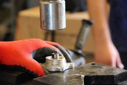
Picture a factory fixture that holds a part while an operator prepares it for the next step. A cylinder closes a clamp and pulls it open again. The pump can be across the machine, inside a power unit, while the cylinder sits next to the work. Hoses or pipes connect them. A valve changes which side of the cylinder receives oil. The layout lets the machine put the motion where the work happens.
Hydraulics works on the same principle in many different applications. A loader raises an attachment. A press pushes a tool. A conveyor may use a hydraulic motor to turn a drive roller. The load, position and control arrangements differ. The shared idea is that a pump supplies fluid, the circuit routes it and the actuator delivers motion under the right conditions.
Start by naming the motion you want to understand. “The clamp opens” gives you a specific actuator and an operating state. “The hydraulics don't work” could describe the whole machine, a single function or the control signal that starts it. Once the motion has a name, you can follow its oil path and identify which parts share the same pump and return.

The main hydraulic system components and what they do
A reservoir stores the oil in an open-circuit system. A pump supplies flow. Valves direct the flow, limit or control pressure, or regulate the amount of oil sent to a function. An actuator turns hydraulic energy into movement. The lines between parts carry the oil. Filters manage contamination, and a cooler helps manage heat when the design needs one. A single machine can have several branches with their own valves and actuators. Bosch Rexroth, Hydraulics Basic Principles, basic circuits
| Part | Job | What a buyer should recognize |
|---|---|---|
| Reservoir | Stores oil and supplies the pump inlet in the example circuit | Oil level, usable capacity and the paths that return oil to the tank |
| Driver and pump | The driver turns the pump, which delivers oil flow | Power source, pump type, direction, intended flow and pressure range |
| Directional control valve | Opens particular paths to make the actuator move in the intended direction | Spool positions, pressure and tank connections, and work ports |
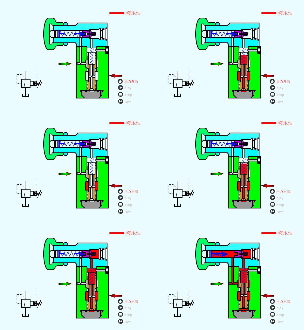
| Pressure control valve | Limits or manages pressure in the relevant part of the circuit, according to valve type | Which connection and circuit condition its function applies to |
| Cylinder or hydraulic motor | Delivers straight-line motion or rotation | Stroke and force for a cylinder, or speed and torque for a motor |
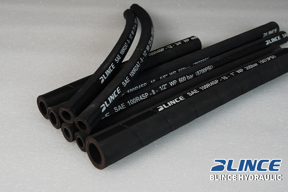
| Hoses, tubes and fittings | Connect the parts and carry the fluid | Working pressure, fitting and seal type, routing and bend space |
| Filter or cooler | Helps control contamination or temperature | Whether it is installed in pressure, return or another specified path |
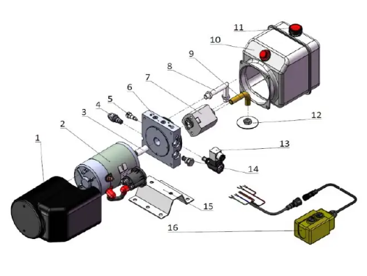
Look for groups of components on a machine drawing. A drive motor, reservoir, pump and some valves may come together as a hydraulic power unit, often called an HPU. The full system includes the connected actuators and controls that do the work. A buyer comparing hydraulic power unit suppliers should establish which components are included in the unit and which are already part of the machine.
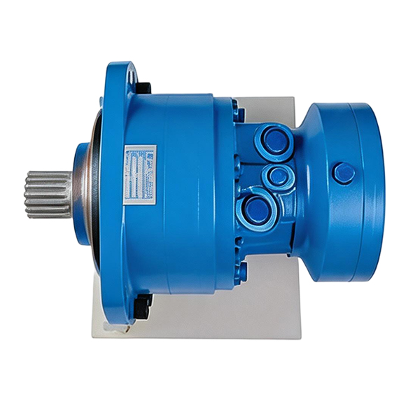
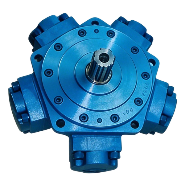
The word motor comes up twice in this example. An electric motor can run the pump. A hydraulic motor, if the machine uses one, sits on the output side and uses the oil to drive something. The pump itself converts incoming mechanical power into fluid power. Trace what each shaft connects to if you are sorting out what to buy.
What the pump does when the machine needs force
A pump moves oil into the circuit. Pressure builds according to the load and the restrictions the oil meets, within the behavior and limits of the pump and controls. A lightly loaded cylinder can move with a lower pressure than the same cylinder working against resistance. A pressure control can respond as its design calls for when a set point is reached. A pressure figure on a nameplate is a rating or specification, so the circuit and measurements establish the working value.
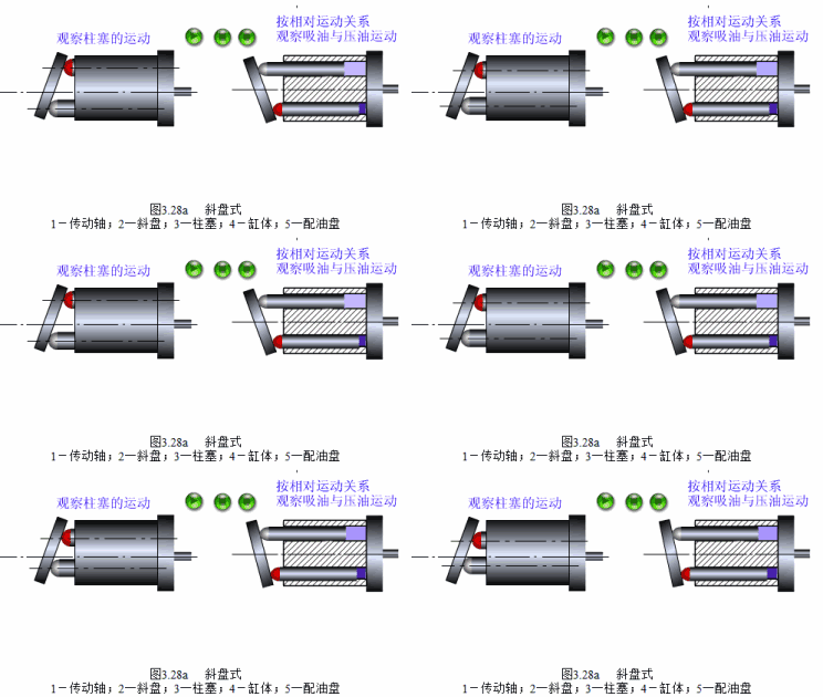
Some pumps deliver a fixed theoretical amount of oil per shaft turn. Their actual delivery depends on speed and leakage. Others can vary their displacement to change how much oil they supply. For a buyer looking at hydraulic pump types, that distinction affects what the pump and control system do when no actuator is asking for movement. An existing valve and its neutral paths are part of the comparison.
Follow the oil as the cylinder moves
Use a simple open circuit for the example. An electric motor turns a fixed-displacement pump. The pump draws oil from a tank, feeds a directional valve and has a specified pressure relief path. The valve controls a double-acting cylinder. A double-acting cylinder has a connection to each side of its piston, allowing oil pressure to produce motion in either direction. In this schematic, setting the valve to neutral leaves a route from pump to tank and blocks the two work ports at the valve itself. HAWE fluid lexicon, open circuit
When the rod extends
In the example, the pressure line reaches the valve at P. One valve position sends that oil out through A to the chamber at the closed end of the cylinder. The piston moves and the rod extends. At the same time, the rod-side chamber sends oil back through B. The valve connects B to T so that oil can continue toward the tank.
Think of the two paths as one event. Oil arriving on one side and leaving the other side gives the piston room to move. The actual machine may have other components that manage speed, load or safety. A separate load-holding valve, for example, can affect when the actuator is allowed to move. This example describes the basic paths through the directional valve.
When the rod retracts
The valve connects P to B and A to T. Incoming oil reaches the rod side and pushes the piston in the other direction. The closed-end chamber sends its oil back through A. The piston rod retracts. In this movement, B is the supply work port and A handles return, so the roles switch as the valve changes position.
The letters identify where the hoses connect. On another machine, A could go to the rod end and B to the other end. The drawing and the routing tell you whether a particular command extends a rod, retracts it or turns a hydraulic motor. In a linkage, the machine may even raise a load when the cylinder retracts. That is why a useful valve inquiry describes both the commanded movement and the actuator's connections.
When the operator releases the control
On our spring-centered valve, releasing the control returns the spool to the selected neutral position. The spool is the part that moves inside the valve to change the oil paths. In this design, P connects to T so the fixed-displacement pump has a return path. A and B are blocked at the directional valve. The supply can continue moving while the actuator is at rest.
Another valve may block P and T at center, or connect one or both work ports to tank. Different pump controls and upstream arrangements can make those neutral states appropriate on different machines. Check the system schematic and the exact valve's center symbol together. A blocked path in a symbol is a description of the directional valve. Holding a load safely depends on the machine's approved load-holding design and service instructions. Bosch Rexroth ED-IP directional valve data sheet, spool variants
What P, T, A and B mean on a hydraulic valve
The table shows the flow paths together. They apply to the example, with A at the closed end, B at the rod end and a neutral passage from P to T.
| Valve position | Supply path | Return path |
|---|---|---|
| Extend | P → A → closed end | Rod end → B → T |
| Retract | P → B → rod end | Closed end → A → T |
| Neutral | P → T toward the tank | A and B are blocked at this valve |
The four letters name the connections on the valve body.
| Port | Common meaning | Example path |
|---|---|---|
| P | Pump or pressure supply | Pump outlet to valve inlet |
| T | Tank return | Valve return toward the reservoir |
| A | Work port A | To the cylinder's closed end in our example |
| B | Work port B | To the cylinder's rod end in our example |
In a common 4/3 directional valve symbol, the four ways are the main hydraulic connections and the three positions are shown as separate boxes. Look at the arrows and blocked ends in the box that applies. On a spring-centered 4/3 valve, the middle box usually describes the neutral position. See the exact manufacturer's drawing for the port locations and options. The tank return can have a pressure limit of its own. HAWE SWPH 10 technical data, port designations and permitted T pressure
An existing valve may look like the P40 directional control valve, a monoblock family with the functions built into one body. Use a series name to narrow the search, then confirm the precise code and symbol. The circuit in this article illustrates a selected neutral arrangement. For a broader comparison of ports, flow and controls, consult the guide to choosing a directional valve by its circuit and spool.
How pressure and flow affect the work
Pressure and flow answer two different questions about the machine. Pressure acting over a cylinder area creates force. Flow fills that area as the rod moves, affecting its speed. If the load grows, the pressure required to move it can rise. If pressure is available but part of the flow goes to another function, the original function can slow down. What you see depends on how the circuit controls or shares its supply.
Take a hypothetical single-rod cylinder with a 50 mm bore and a 25 mm rod. Assume 100 bar gauge at the closed end during extension, negligible pressure on the return side and no friction or leakage for the calculation. The closed-end working area is π × (50 mm ÷ 2)², or about 1,963 mm². At 100 bar, the pressure is 10 N/mm². Multiply by the area to get approximately 19.6 kN of ideal extension force at the cylinder. Actual force also depends on the pressure acting the other way, plus friction and the particular mechanism.
If the cylinder receives a steady 10 L/min at that same side, that is about 166,667 mm³ per second. Divide by the 1,963 mm² area to get an ideal rod speed of about 85 mm/s. For a 250 mm stroke, a steady motion at that speed would take around 3 seconds. A machine can take longer because of acceleration, end cushioning, flow changes and other controls. The example illustrates how to tell a force requirement from a speed requirement. It is separate from the allowable load at a clamp, table or attachment. Bosch Rexroth, basic hydraulics and force transmission
| What the machine needs | First figure to confirm | Where to look next |
|---|---|---|
| More push at the same position | Load force, cylinder area and pressure on both sides as applicable | Cylinder rating, linkage and the approved circuit limits |
| Faster movement with the same chosen cylinder | Flow reaching the cylinder under the actual operating conditions | Work-port and return paths, pump delivery and concurrent functions |
| The same time in both directions | Cylinder areas and how the two strokes are controlled | Directional and flow controls, active loads and machine requirements |
| A longer or repeated cycle without interruption | How long each motion takes and what happens between motions | Pump and actuator duty, heat rejection and oil conditions |
On the rod side, the rod takes up part of the piston area. At the same incoming flow, a typical single-rod cylinder can retract faster because oil is filling a smaller effective area. In this example, the 25 mm rod leaves an effective area of about 1,473 mm². With the same 10 L/min supplied to the rod side, the ideal retracting speed is about 113 mm/s. Since the cylinder now empties its larger chamber, it returns about 13.3 L/min through the valve during that steady movement. This is a reason to specify return flow for the part of the cycle that produces it. In practice, the circuit may limit one movement or provide a controlled speed in both directions. The machine's intended behavior gives you the comparison point.
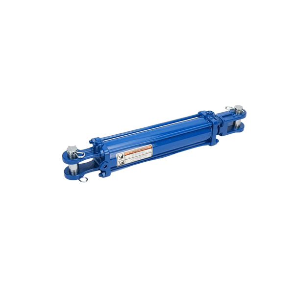
When the machine needs to push, pull or hold through a defined stroke, a double-acting HOB series cylinder is a catalogue example of that actuator family. You still need the bore, rod, stroke, load and mount for the exact application. When the output makes repeated complete turns, start by checking whether the work needs a cylinder or a hydraulic motor before comparing component sizes.
What happens to the oil on the way back?
A return line can lead through a filter, a cooler or both, depending on the design. A return filter helps remove particles from fluid before it circulates again. A cooler transfers some heat out of the oil. These components can share a path, but they address different problems. Warm oil alone does not identify the place where power is being lost. A restricted path, long periods of bypass flow or changing ambient conditions can affect what the operator notices.
The tank line has moving fluid and can develop backpressure. Long lines, fittings and components can contribute to resistance. Some manufacturers set a different allowed pressure at T than at P or at the work ports. This matters when checking a replacement valve or changing the return arrangement. A separate case-drain line from a motor or pump can have its own routing and limit. Follow the tag on the schematic to find which circuit you are looking at.
With a common tank and several return paths, always name the line you mean. The return from a cylinder tells you about flow sent back after an actuator movement. A separate case drain may carry leakage out of a housing. An unloading valve may return pump flow during idle. They can all lead toward the reservoir while carrying oil under different conditions. Their functions help identify the right fitting, filter or line from a parts drawing.
A filter has to suit the location where it is used. A housing selected for a return circuit has a particular working pressure and flow specification. A long cylinder retracting at speed can send more flow than expected through that return path. When a machine supplier specifies a filter or cooler, include the flow and the line where the unit sits. Checking just the pump's nameplate flow may leave out what actually returns during that movement.
Open circuit or closed circuit?
In an open circuit, the pump draws oil from a reservoir and the main working flow returns to the reservoir after doing its job. That is the layout in the cylinder example. In a closed circuit used for some hydrostatic drives, the motor's main flow goes directly back to the pump. A separate charge circuit supplies make-up oil and can support additional functions. A closed-circuit drive can still have a reservoir, filter, cooler and drain lines. HAWE fluid lexicon, closed circuit
A vehicle can use both layouts. Its travel drive may have a closed main loop, while a separate machine function uses a cylinder in an open circuit. Find the pump and actuator responsible for the movement in question. The way oil returns matters when you compare a pump or valve. It helps the supplier identify the displacement control, charge arrangement or neutral path that belongs on that machine.
The terms open center and closed center describe valve or circuit arrangements at neutral. They are a different question from whether main working flow normally returns to a tank or directly to a pump. A valve can have work ports blocked in neutral while another internal path returns supply oil to the tank, just as in the simple cylinder example. In a replacement inquiry, the actual valve symbol is more useful than an isolated label such as “open.”
How to describe a machine problem before ordering parts
First say whether the machine is a new build, a direct replacement or a fault investigation. For a new build, define what the machine has to do and when. For a direct replacement, gather the existing model and interface drawings. For a fault, describe the motion that changed and under what conditions. A brief that starts with the operating state gives the supplier a path to follow.
If every function is slow, record when that began and what changed near the same time. The functions may share a pump, driver or supply path, so inspect the machine documentation to see what they have in common. If one function is slow while others operate normally, say which valve section, cylinder or motor is involved. The evidence may point toward that branch, although shared supply can still affect it. A qualified service technician can then decide which checks fit the actual system. BLINCE guide to tracing power-unit pressure loss
If the system works normally when cold and slows after a long run, note the time and temperature if you have an approved reading. A supplier can use that information together with the normal duty and component codes. A pressure reading by itself rarely isolates the cause. It matters where the reading was taken, what the machine was doing and whether the actuator actually received the expected flow. Save photographs of the gauges and labels with the context that explains them.
A machine can behave differently after a replacement even when the new part fits. A directional valve can put the oil on another path in neutral. A cylinder of a different bore can take longer to fill. A pump with the wrong supply behavior can change several functions. Ask the seller to compare the operating function along with the mechanical connection.
Use the manufacturer’s instructions and qualified service personnel for any pressure measurement, isolation, load support or removal. Stored hydraulic pressure and moving or raised parts require the machine’s service procedure. A drawing, an operator's description and visible part labels are enough to start a purchase discussion without changing the circuit.
What to send with a hydraulic system inquiry
Name the movement in plain words. “The existing cylinder must close a clamp over a 250 mm stroke, then open before the next part arrives” is more useful than a list of part names. Describe what happens if there are two functions or a change in speed. If the equipment will work through a predictable cycle, include the number of cycles or the time spent doing each operation.
| If you are buying | Send this information when available | Ask for this in return |
|---|---|---|
| A pump | Driver, current pump code, circuit type, required flow and pressure, mount and shaft | Whether the type, control, ports and speed match the application |
| A directional valve | Full valve code, schematic, movements and neutral path, flow, pressure and mounting | Confirmation of spool symbol, port layout, return requirements and options |
| A cylinder | Stroke, load and direction, bore/rod if known, mount dimensions and working pressure | Drawing with cylinder dimensions, connections and the relevant working conditions |
| A set of components | Machine sequence, functions that must operate together, load and available hydraulic supply | A clear component list, interfaces and any data needed before confirming the match |
If the conversation concerns the entire system, agree on which parts the supplier is reviewing. A pump and valve package may omit the cooler, hoses, control panel or actuator, even when all of those appear on a drawing. Defining the package also helps you compare offers from different suppliers. See the hydraulic system supplier guide for a broader sourcing comparison.
Send BLINCE the machine type, the motion you need, and the existing diagram or model code if available. Include the working flow and pressure when you have them, along with the position or operating state they came from. If you know just one missing detail, such as the valve's neutral position, mark it as unconfirmed on the drawing. That gives the supplier a concrete item to check.
Common hydraulic system questions
Does a pump make pressure or flow?
A pump delivers flow. Pressure develops as the load and circuit resist that flow, with the working value shaped by pump and valve controls. A gauge reading can change as the load changes while the same pump is still installed. Use the pump's rating to check the allowed conditions and the schematic to trace the actual supply path.
Why can a hydraulic cylinder be slow even when pressure looks normal?
Its speed depends on the flow reaching its working chamber, its area and how the circuit controls movement. A gauge at the supply may miss what is happening in the branch. Note whether the speed changes with other functions running, on one stroke only or after warmup. That context helps identify which check should come first.
Can I replace a hydraulic valve if all the threads match?
Thread compatibility is one part of fit. The valve must also have the intended work and neutral paths, pressure and flow capabilities, control arrangement and mounting. Compare the exact symbols and full model codes. A visual match is a starting point for comparing documents.
Why is there a relief valve in the system?
A relief valve opens a path when its inlet pressure reaches the conditions for operation, according to the valve's design. In the example it can return oil toward the tank to limit pressure in the protected path. Oil moving across a large drop can create heat, so a machine's normal pressure and idle behavior are part of the circuit design. Check the machine documentation for the relevant valve and approved setting.
How do I read a hydraulic circuit drawing for the first time?
Pick one movement and find the actuator doing it. Start at the pump, follow the supply through the valve position for that command, and trace where the oil leaves the actuator. Then do the same for neutral. On a complicated drawing, keep the component names and connection tags next to each path. You can ask a clearer sourcing or service question once you know where your tracing stops.