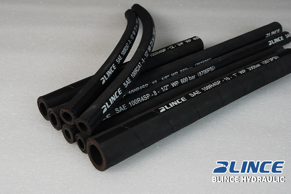

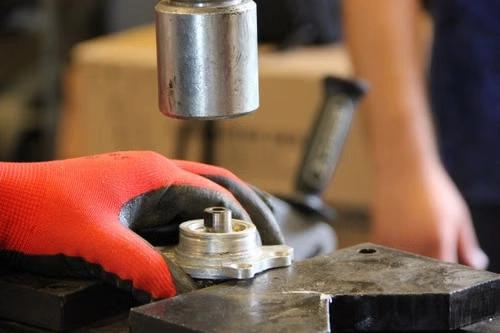
To identify a hydraulic fitting, check the thread and the place where the connection seals. A JIC fitting seals on a 37° seat. An ORFS fitting seals with an O-ring on a flat face. An O-ring boss connection seals at the equipment port. For example, some JIC and ORFS ends share a 9/16-18 thread, but their sealing faces are different. For a hose assembly, identify both ends separately and record what each one connects to. That is a more useful starting point for a replacement order than the hose diameter or the size of the wrench that fits it. Gates Safe Hydraulics Pocket Guide, coupling identification
Start at the connection the oil could escape through
A fitting is often described by the part you can see most easily. A service photo might show a hex nut, and a parts request might say “a half-inch elbow.” The actual seal is often inside that connection. Depending on its design, it could be two metal seats meeting, an O-ring pressed against a surface, a seal under a shoulder, or a tapered thread joined according to the fitting manufacturer's instructions.
Picture a hose from a valve to a small loader attachment. At the valve end, a short adapter is screwed into the body. The hose nut attaches to the outer end of that adapter. On the attachment end, another adapter or a quick coupling may be used. The valve port, the adapter, the hose end and the coupling each have their own interfaces. When one piece needs replacement, mark exactly where it separates on the assembly drawing.
The same fitting body can also have a different connection at each end. A port connection that uses an O-ring at the valve can lead to a JIC flare for the hose. Ask for the two mating standards even if only one side is visible. The thread that holds the adapter into a valve and the one on its exposed nose can both be worth recording, especially if the replacement order includes the adapter.
Which part are you buying?
| Part | Where it goes | What a buyer needs to identify |
|---|---|---|
| Hose end fitting | Attaches to flexible hose and connects the assembly to a mating port, adapter or coupling | Hose type and size, approved end fitting series and the port-side connection |
| Adapter | Provides a connection between two interfaces, or changes direction or mounting | The complete connection at each end, plus the geometry and working requirements |
| Tube fitting | Joins rigid tubing to another component or length of tubing | Tube outside diameter and the exact fitting system, seat, seal and series |
| Quick coupling | A plug and socket designed for their specified attachment and disconnection conditions | Coupling profile, size, series and the connection on its back end |
That distinction makes a service request easier to read. “The hose nut has damaged threads and the adapter stays in the cylinder” gives a clearer starting point than “the cylinder fitting is bad.” When you have an assembly already removed by the service team, keep it available with a sketch or a clear photograph of its original location. A wrong assumption about which part was replaced previously can produce another order for the wrong interface.

Common hydraulic fitting types and where they seal
Start with the sealing surface. Compare it with a dimensional chart or drawing that describes the actual connection. The table gives common examples that appear on mobile and industrial equipment. Each row describes an interface family. Size, material, construction and manufacturer conditions still matter within that family. Gates hydraulic hose and fitting catalog, sealing types and identification tables
| Interface | What holds the parts together | Where to look for the seal |
|---|---|---|
| JIC 37° flare | Parallel threads on the fitting and nut | Angled metal seats meet at the flare |
| ORFS, or O-ring face seal | Parallel threads on the end and nut | An O-ring in a groove on the male face compresses against a mating flat face |
| SAE O-ring boss, often called ORB | Parallel threads engage the equipment port | An O-ring at the base of the male stud seals at the port |
| BSPP, or British Standard Pipe Parallel | Parallel pipe thread | A separate cone, washer, bonded seal or O-ring according to the actual end design |
| NPT or BSPT | A tapered pipe thread in a matching arrangement | The threaded engagement is part of the seal, subject to the design and the approved sealing method |
| Metric 24° tube fitting | A metric thread in the documented design | A defined 24° connection, with the cutting ring, mating nose or seal specified for the variant |
| Hydraulic flange | Clamps or bolts retain the flange connection | An O-ring or other seal in the location specified by the flange design |
JIC flare and ORFS face seal
A common JIC hose end has a nut that turns while a conical seat inside it mates to the angled nose of the other end. The threads pull the seats together. A face-seal connection can use a swiveling nut too, but the surface it presents to the male fitting is flat. Look straight at the end, rather than trying to infer the seal from a side photo of the nut. If you can see the mating male piece, include its face and thread in the photograph.
A similar thread is a real source of confusion. In common size tables, a 3/8-inch tube-size JIC 37° connection and a 1/4-inch tube-size ORFS connection can both use 9/16-18 threads. The JIC face has an angled seat. The ORFS face has a flat sealing arrangement with an O-ring on the male side. A 9/16-18 reading alone therefore leaves the fitting unidentified. Look up the exact standard and size before asking for the part. RYCO JIC 37° thread chart · RYCO hydraulic hose catalog, ORFS thread chart
The sizes in that example describe the catalogue's connection series. They do not give the size of any hose attached to it. A hose fitting can be selected to connect the hose size and the equipment-side connection needed for the assembly, from combinations that the supplier approves. In a written order, use separate fields for hose inside diameter and connection size.
JIC is also often described as a flare, but other flare standards exist. Where a catalogue shows a 45° seat or a regional connection that looks similar, the angle and mating drawing matter. If the old seat is crushed or badly marked, measure an undamaged counterpart using the proper reference or find the equipment maker's port specification. A photo gives a useful clue to the family even when the full standard still has to be checked.
O-ring boss and other straight-thread port ends
An ORB fitting goes into a matching port. Its O-ring sits close to the shoulder or base of the fitting threads and seals at the port interface. ORFS puts the seal on the outward-facing connection. A single adapter can have one pattern at the equipment side and the other at the hose side. Write both out in full the first time you specify an unfamiliar assembly.
A straight thread on another equipment port can have a different sealing surface. Some ports use a sealing washer or a bonded seal under a shoulder. Others have a defined contour for a particular O-ring. A drawing with only thread major diameter and pitch can still leave the sealing detail open. When sourcing an adapter, ask which end seals against the port and where the seal sits relative to the face of the valve body.
A 90° port adapter can also have an adjustable orientation arrangement. It has a particular sealing and locking design, which belongs in the parts comparison. A supplier needs both installed orientation and the matching port requirements. A hose swivel nut and an adjustable adapter are separate features, even when both allow alignment during installation under their specified procedure.
BSP parallel, BSP taper and NPT
BSPP describes a parallel thread, frequently called a G thread on drawings. Common hydraulic connections using it can seal on a cone or at a separate washer, O-ring or port face. When someone asks for “BSP,” record whether the thread is parallel or tapered and capture the seal style. The same broad pipe thread name can cover connection shapes used in different places on a machine.
BSPT and NPT are tapered family names. A person comparing two old parts can recognize a slight taper and still need to confirm the standard, pitch and mating part. At some sizes the dimensions are close enough to cause confusion. Use the equipment drawing or each maker's fitting chart to distinguish the threads. The appearance of a tapered connection does not establish which sealing practice or dedicated mating port applies. Swagelok thread and end connection identification guide
Nominal pipe size is another source of mistaken orders. A designation such as one-quarter inch does not mean calipers will show a quarter-inch male thread diameter. The number is a pipe-size designation. Use the measured diameter and pitch to locate the appropriate row on the manufacturer's chart. Leave the candidate size unconfirmed if the taper or form remains ambiguous.
Metric 24° connections and flanges
Metric only tells you something about the thread system. It does not identify the sealing face or the tube series. On common 24° tube connections a buyer may need to specify light or heavy series and the tube outside diameter. A hose end made to mate with a particular 24° end may have an O-ring nose, depending on its exact design. Look for the mating configuration in both parts of the drawing. The hose size is still specified separately.
A split-flange connection uses a different way to hold the parts together. The flange head, clamp and bolt pattern have dimensions that matter. The face seal has to match the design. A quotation that says only “four-bolt flange” leaves too much open. Request the flange pattern and dimensional standard, working pressure requirements, seal and hardware information for the specific assembly. The orientation of an elbow leading into the flange may also be needed on a tight machine.

How to identify an unknown fitting from a removed part
Ask the machine service team to follow the approved procedure for isolation, stored pressure and load support before removing any connection. The identification steps below use an already isolated, removed component or a drawing. They help describe the replacement. The fitting and machine documentation govern acceptance and installation. Gates Safe Hydraulics Pocket Guide, safe maintenance and coupling identification
Identify the side you are examining
Give the connection a location in the assembly. “Valve end, hose detached from the adapter” tells the next person which threads matter. Photograph the removed piece from the side to show the body shape and from the front to show the seal face. Add a photo of the adapter or equipment port it mates with. If the part is in a chain of adapters, number the pieces in installed order on a simple sketch.
Record whether you see an internal or external thread. The nut can conceal the edge of a seat, particularly on a hose end. A clearer photo from an angle can show whether there is a flat face, a cone or an O-ring groove. An O-ring removed during an earlier repair may no longer be present. Look for its groove and compare it with a drawing rather than assuming the seal was never part of the connector.
Record thread dimensions and the seal separately
A caliper can help record the outer diameter of an external thread. A pitch gauge can distinguish common metric pitches or inch threads. A tapered thread is measured at the reference area specified by the chart or identification guide. For an internal thread, use the applicable measurement method rather than writing down the wrench opening or interpreting a photo scale as the thread diameter. Put units beside each value.
A seat gauge or a matched manufacturer's drawing can help identify a cone angle. Angle references vary across fitting drawings. One diagram may show a half-angle and a different drawing may show an included cone angle. Before comparing values, verify what each drawing is measuring. If the actual seating face is damaged, note that the angle is uncertain. A photograph of the mating part and the OEM drawing can resolve a question the old fitting alone cannot.
| What you can see or measure | Useful note for the supplier |
|---|---|
| Side of the assembly | End A or End B and the part on the machine that it mates with |
| Thread | Male or female, parallel or tapered when confirmed, measured diameter and pitch with units |
| Seat | Cone, flat face, O-ring at the shoulder, flange or another documented shape |
| Angle or size reference | The chart, gauge convention, mating drawing or exact manufacturer part number |
| Body shape | Straight, 45° elbow, 90° elbow, swivel nut, flange or another named arrangement |
| Identification status | Confirmed, candidate or still unknown for each end |
After recording the details, check them against a manufacturer identification chart. A part can fit a thread gauge or appear to screw into another thread without meeting the seal geometry. Avoid using a successful finger-fit as evidence of compatibility. A drawing comparison with the correct connection standard and nominal size gives the shop something it can actually verify.
Work from the better evidence when a fitting has been modified
An existing machine may have more than one adapter stacked at a port. One adapter could be original and another added after a hose failure. If you copy the latest arrangement, you may reproduce an access or clearance problem. If you ask the vendor to match the original, provide the original parts record or port drawing. Identify both situations on the request so the intended scope is clear.
On equipment with identical functions on both sides, a nearby undamaged line may give a useful second example. Check that the equipment actually uses the same part and configuration. A mirrored route can need a different orientation or end. A parts diagram is a better authority on interchangeability than the fact that a hose looks similar from the outside.
Specify both ends of a hydraulic hose assembly
A complete hose order needs the connection at End A and at End B. Begin by naming where each end goes. Then record the thread or flange, the seat, the shape and any orientation needed. If one end is a female JIC swivel and the other end uses a flat-face seal, put that in two separate rows. Most confusion comes from trying to describe both ends with one line such as “3/8 hose with 90° ends.”
Keep three measurements in separate fields. The hose inside diameter describes the flow passage, the connection size describes the fitting end, and the hex size describes the wrench opening. A hose cover marking can identify part of the hose specification but will not identify the mating thread at the valve. The construction and approved fittings belong to the assembly decision at a different level than the port-side thread.
A 90° end may also have a different reach or drop length than another fitting listed with the same angle. On a tight attachment mount, that difference can change where the hose starts to bend. If both ends are angled, document the orientation of one relative to the other with a stated viewing direction. Match production length and measurement references using the existing guide to measuring the old hydraulic hose assembly.
An example purchase record
Suppose a distributor is quoting a replacement line for an attachment. The hose at the valve goes through an adapter, and the equipment owner intends to keep that adapter in place. Its exposed end has already been identified from the original drawing. The connection at the attachment is dirty and the seal face is unclear. A useful request can include the confirmed first end and a targeted question about the second.
| Order field | Example of a clear entry |
|---|---|
| Equipment and line | Attachment work line, from the valve-side adapter to the attachment manifold |
| End A | Confirmed from the drawing as a female JIC 37° swivel hose end, exact size per the matching adapter |
| End B | Elbow layout photographed. Family and size to be confirmed from mating-port drawing |
| What stays on the machine | Existing valve-side adapter |
| Hose and working conditions | Copy the legible hose markings and include pressure, fluid, temperature, routing and measured assembly length |
| Next decision | Confirm End B and approved hose/fitting combination before pricing the assembly |
That request is usable even though part of the identification is still open. The supplier can ask for the specific drawing or photo needed for End B. It also keeps an unconfirmed fitting from becoming an implied purchase authorization. If the goal is to standardize several old machines, make a separate entry for each machine or port that has not been verified.
How ratings and the assembly system affect the choice
The hose, end fitting, hose-to-fitting attachment and adapter together have to suit the operating conditions. A rated fitting cannot raise the working rating of a lower-rated hose or assembly. Use the verified assembly and component limits for the compatible combination, including any relevant temperature, fluid and impulse conditions. Two parts that can mate at the port may still require different hose fitting series on the other side.
Manufacturers specify hose and fitting combinations and assembly data. Do not infer crimp compatibility from the outside diameter of an old shell or the label of a product family. When discussing a hydraulic hose type, send the layline or exact data sheet so the supplier can check the right assembly system. The assembly provider should identify its approved components and relevant production checks. Gates hydraulic hose and coupling catalog, assembly and compatibility guidance
If you are starting from the BLINCE hydraulic hose range, describe the intended duty and end arrangement before reviewing the specification. A listing such as the SAE 100 R7 hydraulic hose identifies a product family to discuss. Hose condition, the actual specification and approved fitting series determine whether it belongs in a particular assembly. No product link can establish the thread at the other end of your machine.
The fluid and temperature can affect elastomer suitability. An O-ring fitting identifies the type of interface. It is still necessary to verify the seal specification for the fluid, temperature and applicable manufacturer requirements. Exposure to outside abrasion, movement and limited bending space also matter to the complete hose. Photos of the installed route can help clarify whether the fitting shape and the hose design are suitable.
Keep quick couplings and their back ends separate
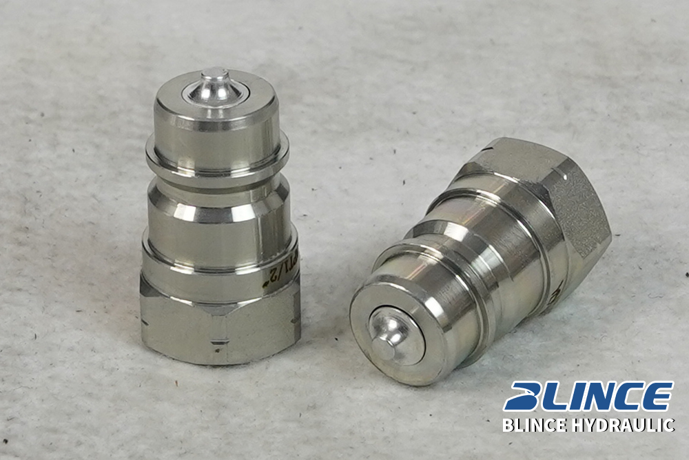
On a detachable attachment, the plug and socket mate using an identified coupling profile, while the rear thread or connector attaches that coupling to the hose or port. A male plug and a fitting with male threads are two different descriptions. If you start from the AW32184 replacement quick-coupler plug listing, confirm the counterpart and the precise rear connection for the model in question. Treat that listing as an example of a plug, with exact pairing and limits established from its applicable documentation.
When a customer asks for a coupler together with a new hose, write down the coupling half, profile and size as their own fields. Record the connection where it joins the hose as another field. An adapter may sit between the two. Leaving it out of the request can confuse a correct coupling choice with the wrong hose-end choice.
Mistakes to catch before an order goes out
Ordering by the wrench size. A hex may be common to more than one nut or connector. Write down the thread diameter and pitch and photograph the sealing end. Keep the tool size as an access detail if it matters to the installation.
Matching the visible thread and overlooking the seat. A cone and a flat face can require different mating pieces even when the thread measurements match. Move the sealing profile into its own field in the order. If the supplier asks for the mating drawing, send it with the measurements.
Copying only the leaking end. The old hose may have two different end standards, and there may be an equipment adapter at one side. Label both before requesting the assembly. Record each planned retained component so that the quote covers the parts you actually want to replace.
Treating a family name as a rating. A JIC or BSPP description tells you a connection family. Check the exact construction, fitting series and working data. Include operating pressure and conditions for the completed assembly and any adapter in the oil path.
Changing the angle to solve an access problem without a drawing. A different body can affect the hose's usable length, bending space and clearance. Record the desired orientation and a view of the adjacent frame or body wall. The person quoting the assembly can then see which dimensions have to be checked.
What to send for a fitting or hose inquiry
For a fitting or adapter, send both mating interfaces, the full part or equipment code if readable, and clear photos of the body and sealing faces. Indicate the desired straight or elbow layout and any clearance limits. Give measurement units and mark uncertain dimensions as preliminary. A catalog number from one manufacturer can guide a comparison, but the geometry and working conditions must be checked for the chosen product.
For a complete hose assembly, provide the hose marking or its specification, the two end entries, the measured assembly length reference, and the orientation of both elbows if applicable. Add pressure, temperature, fluid and the equipment duty where they affect the assembly choice. These details help you compare what a hydraulic fitting supplier can document for the application.
Send BLINCE your actual fitting or hose requirements. If the part number is missing, share the port or matching end and at least two clear views of the removed fitting. Name the part that stays on the machine. A useful first reply can identify what the evidence supports and which measurements will confirm the order.
Common fitting identification questions
Can an ORFS fitting and a JIC fitting use the same thread?
Yes. Some matching thread designations occur across the two families. Their sealing faces differ. Use the thread chart and the matched face to confirm the exact connection before choosing a replacement.
Does BSPP seal on the thread?
BSPP is a parallel thread description. Hydraulic fittings using it normally have a separate sealing arrangement. Find out whether the actual connection has a cone, washer, bonded seal or another documented design before ordering.
Does a dash size identify the hose and fitting end together?
Use the catalogue to see what that dash size refers to. A hose dash size usually describes a hose size, while a dash designation on the connection side can refer to the fitting series or tube size. Record both and include the full connection designation.
Is an O-ring at the base of the thread the same as an O-ring on the face?
The positions describe different sealing interfaces. An O-ring boss design seals at a port near the base of the stud. An O-ring face seal places the O-ring on the face of the male connection. A drawing or undamaged mating part will help you confirm the exact family.
What if the fitting has no label and the seat is damaged?
Identify the component it mates with, photograph the connection location and obtain the original port or hose drawing if available. Record what can be measured and flag the damaged sealing surface. An exact replacement depends on confirming the interface, not on estimating a missing dimension from one photo.