
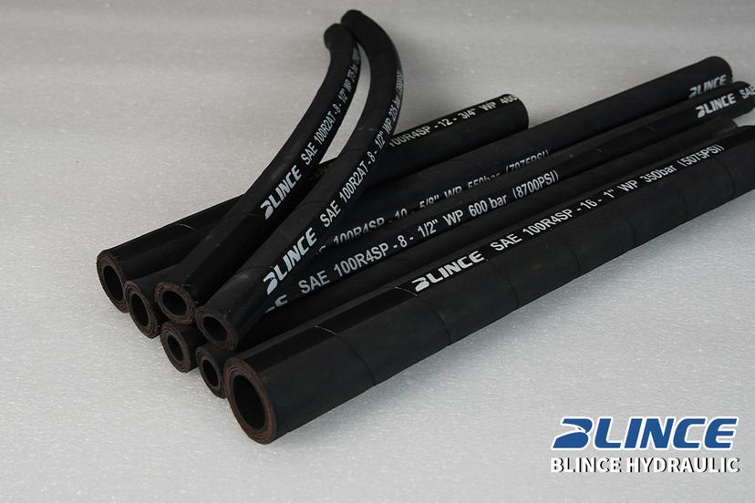
For a hydraulic hose replacement, measure the complete assembly between the reference points used for its end fittings. Label the two ends, record how any elbows point, and confirm the hose still has room to move through the machine’s working range. Mark both measuring points on a photo or drawing. If the old hose rubbed, kinked or pulled tight, photograph its installed route and check what changes as the machine moves before copying the old length.
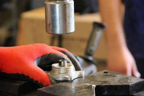
Photograph the installed route before the old hose comes off
Start with the equipment model and the function the hose serves. A line to a moving cylinder has a different job from a fixed return line nearby. Take one photo that shows the whole route, then label the connections End A and End B on detail photos. In your notes, describe where they go. “End A at the bulkhead near the boom pivot” gives the supplier more to work with than “left end,” especially when the pictures were taken from opposite sides.
Document the route at the normal inspection position. Show the clamps, supports, protective sleeves and nearby parts that could touch the hose. If it runs behind a panel, photograph the entry and exit and note what sits between them. Include the failed area in a wider picture. A polished patch where the hose crosses a bracket tells a different story from a tight fold immediately after a fitting.
Treat this as a record of the machine before disassembly. Trapped pressure and stored loads can remain after shutdown. Follow the equipment manufacturer’s isolation and depressurization procedure and support any movable parts as specified before handling the assembly. A qualified technician should handle removal, movement checks and testing. If a leak is suspected, keep clear of the area and follow the approved leak inspection method. A hand is never a pressure leak detector.
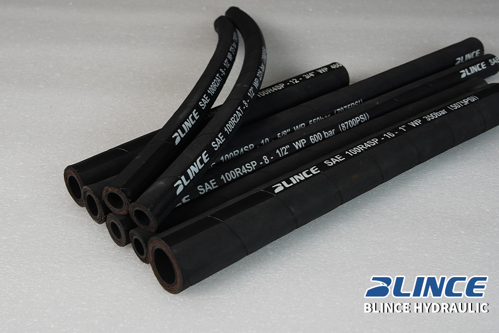
Once the machine is safe and the hose is off, preserve any readable markings and the connection identity. Oil residue, paint and a rotated elbow can hide useful information. Record the hose layline, which is the printed identification along its cover, as well as any assembly tag or OEM part number. The layline can identify a hose family and size, while an assembly number may identify the complete hose and both ends. Send both when available.
Decide whether the old assembly is a good pattern
An original assembly that worked through its service life may be a useful pattern once its dimensions and ends are confirmed. An improvised replacement that failed quickly needs more scrutiny. Compare the old assembly with the OEM parts information and the machine’s route before copying it. Ask whether someone added an adapter, moved a clamp, changed the cylinder or replaced a straight end with an elbow.
Check how the damage lines up with the machine. A cover worn at a repeatable contact point suggests you should review the route and available clearance. A hose that pulled at an end when an attachment reached its limit suggests a movement or support check. A visible kink makes the old curve a poor template. These observations help decide what to inspect. They do not establish why the assembly failed or which hose specification is suitable.
Sometimes the old assembly is incomplete. A missing end or a hose cut during removal removes a key reference. Save the pieces, record what is missing, and work from the OEM drawing or the machine’s approved route with the supplier. Measuring a torn part as though it were intact can turn an approximate dimension into an incorrect purchase specification.
| What you have | Best evidence for the next step |
|---|---|
| Original assembly with readable part number | Part number, A/B photos and a check of the current connection and route |
| Complete old hose with unreadable printing | End references, fitting identification, route photos and machine duty information |
| Damaged or incomplete assembly | OEM drawing or verified machine dimensions with the missing measurements flagged |
| Old hose with an obvious contact or bend problem | Photos of the damage in place and the route at the operating positions that matter |
Measure the finished hose between agreed endpoints
Hydraulic hose assembly length describes the completed part, with both fittings installed. Lay the removed hose on a stable surface in a relaxed position and measure between the applicable reference points for its ends. A supplier may use a sealing face, the end of a connection or an elbow centerline, depending on the fitting design and its drawing. Mark the points on a photo or sketch so both sides can read the same dimension.
A straight assembly is usually easier to describe. With two elbows, the longest distance across the metal is easy to measure but may be different from the specified overall length. If a drawing uses the centerline of an elbow’s connection, the outside edge of the elbow body is the wrong endpoint for that dimension. Put the tape in the photo and mark the line it is measuring. The goal is to give the shop a reproducible dimension, even when the first measurement is provisional.
Measure the hose body in its relaxed shape without stretching it to hit a number. When the hose holds a curve or has been distorted, record how the measurement was taken and use a sketch to confirm what the finished part needs to match. The distance between two ports on the machine is a different dimension. It may be useful for checking clearances, yet it does not include the curved route, straight runs at fittings or movement allowance.
Keep units next to each value. A mixed drawing can legitimately use millimeters for the assembly length and inch descriptions for some fitting threads. If the old part measures about 32¼ inches, write that value with the measurement method and provide millimeters only if the supplier wants a converted value. Let the shop confirm the appropriate manufacturing tolerance. Adding decimal places to a tape measurement does not make it more accurate.
If the assembly is short, the fittings occupy a larger share of the overall dimension. A change from a compact elbow to a longer bent tube can leave less flexible hose between the ferrules even when the total length stays the same. Ask the shop to show the free hose length and the orientation on the proposed drawing when clearance is tight. That is particularly helpful near fixed brackets and machine covers.
Keep assembly length and cut hose length on separate lines
The cut length is the length of the hose before the approved fittings are assembled. It depends on the exact hose and fittings selected and on the end references for the finished part. The Gates hose assembly guide shows a method that subtracts the two fitting cut-off dimensions from the assembly length, using the specified fitting values. Those dimensions come from the appropriate component data, with the same overall-length convention used in the order.
Hypothetical example. A drawing specifies an 820 mm finished length. The selected fittings’ matching cut-off values are 44 mm and 51 mm. The estimated cut length is 820 − 44 − 51 = 725 mm. The 820 mm is the finished dimension the buyer wants confirmed. The 725 mm depends on the assumed fittings and their reference points. If the shop substitutes a different elbow, it needs to check the cut length against the revised component drawing.
| Dimension | Hypothetical value | What to write on the request |
|---|---|---|
| Finished assembly length | 820 mm | Include the marked A and B reference points |
| End A and End B cut-off values | 44 mm and 51 mm | Ask the shop to use data for the proposed fittings |
| Estimated hose cut length | 725 mm | Illustration only, subject to the selected assembly system |
For a first inquiry, put the finished length, end types and orientation on the form. Leave the cutting and crimping data to the qualified assembler using the approved component combination. Where the supplier uses a different length convention, ask for an annotated sketch before releasing the order. This is faster than trying to decide from two unmarked numerical lengths.
Use a marked sketch for a new route
If the old part is unavailable or the layout has changed, mark the connection points and proposed supports on the machine drawing. Include the fittings’ direction, nearby obstructions, the positions in which the machine operates, and the minimum available clearance you can verify. A route measurement should follow the proposed hose path. A taut line between the two ports cannot capture the bends and movement the hose must accommodate.
A qualified installer can assess the proposed route with the equipment secured according to its service procedure. A mock-up or drawing review can show whether the fitting runs into a guard or the curve becomes too tight. Its value is in checking the geometry. The assembler still needs the exact hose family, end fitting dimensions and tolerances to finish the part specification. Keep “route estimate” and “approved overall length” separate in the drawing notes until that review is complete.

Identify both ends and describe how the elbows point
Record End A and End B separately. For a threaded end, take one photo straight at the sealing surface and another from the side showing the thread and shape. Record whether it is male or female, straight or angled, fixed or swivel, and what it attaches to. A dimensioned OEM drawing or verified fitting identification is stronger than a picture alone. Similar diameters can hide different threads, seats or sealing methods.
A flare seats at its angled surface, a face-seal design uses its face and seal, and other fittings seal at a different location. Make sure the connection description names the standard and seal type, not just the wrench size. If the machine already has an adapter, say whether it remains on the machine or is part of the replacement scope. The end of the hose and the port on the machine can be two different connections linked by that adapter.
A flange connection also needs more than a bolt count. Record the flange identity from its drawing and note the seal, the size and the surrounding clearances. If a clamp or fastener appears in the photo, identify which parts the quote should include. When thread or flange identity remains uncertain, ask the supplier to confirm it from the marked dimensions and component documentation before specifying the part. The site’s hydraulic fitting supply guide offers additional context for reviewing connection details with a supplier.
Mark which end you look from to measure elbow clocking
Clocking describes how one angled fitting points relative to the other around the hose axis. An order that says “two 90-degree ends” gives both bend shapes but leaves their relationship unknown. If the elbows must point in a specific direction, mark which end you are looking from, which elbow is the reference and which way the angle is measured. Include a photo or a drawing showing both end directions in the same view.
A sketch is especially useful when the old hose springs into a curved shape after removal. Draw A and B at their intended connections, with arrows showing the direction each elbow points. Tell the supplier which end stays fixed and identify any end that swivels during assembly. Different suppliers can use different angle conventions. Ask them to send back the angle on their drawing so you can compare it with your sketch. For example, a drawing might read “view from A toward B, A points down, B points right.” Both arrows must be shown in that view. The supplier can convert the sketch to its own angle convention and send it back for approval.
A swivel nut lets an installer tighten the connection without twisting the hose. Check the fitting documentation for any movement it permits in service after tightening. If a technician must wind the hose to reach the second port, review the clocking, length and route before accepting the fit.
In a batch order, use a separate line for mirrored assemblies. The left and right parts can have the same length and the same two fittings while pointing in opposite directions. One annotated view per part can prevent a costly mix-up. Include the machine side and revision on the sketch, and keep the approved copy with the purchase order.
Check bend radius and clearance through the working range
A hose that fits at rest may tighten as an attachment extends or form a sharp loop as it retracts. Review the route at the relevant extremes and the transitions between them. Look for the position where the assembly becomes tightest, the point where it can touch another part, and the tightest bend near a fitting. Have a qualified technician use the machine’s approved procedure for checking movement and clearance.
The minimum bend radius comes from the documentation for the exact hose and size. Compare the tightest curve with the supplier’s stated measuring convention and the applicable static or moving duty. The Parker hose safety and product guidance discusses the effects of bend radius, pressure-related length change, machine motion and twist. A hose that can be bent into a space by hand does not establish that it meets its documented limits there.
Leave the manufacturer’s required straight length at the fitting and observe how the curved section starts. A hose pulled sharply around a nearby bracket can bend right at the ferrule while the rest of the loop looks generous. An elbow or a different support location may provide a cleaner path if the machine design allows it. Confirm any route change with the relevant drawing, since a larger loop can move the contact point to another part of the machine.
Inspect both directions of movement. In the extended position a hose can be short of travel and pull on the fitting. In the retracted position the same hose can drop into a pinch point. Near a hinge, where the hose crosses the joint and how it is supported can affect both cases. A wide photo at each position and one close-up of the tightest curve are often enough to show the supplier what the drawing must accommodate.
Look for matching wear marks on a nearby bracket or hose. Where a sleeve or heat shield is proposed, verify clearance for the added thickness through the same range of motion.
Pressure, vibration and movement can affect how the assembly sits. Use the hose documentation and equipment requirements for support and allowances. There is no useful universal percentage to add to an old hose’s length. Additional length might resolve a tight condition at one end of travel while creating a snag at the other. Choose the geometry from the actual route and check the resulting assembly against the limits for that product.
| Route condition | What to give the supplier or installer |
|---|---|
| Shortest or most crowded working position | Photo, available clearance, fitting angle and tightest curve location |
| Longest working position | Route picture, movement direction and where the hose would pull against a support |
| Nearby sharp edge, hot surface or moving linkage | Marked obstruction, distance and whether contact changes with motion |
| Existing clamps or guards | Position, what must remain fixed and the available hose movement |
| Two ends that are hard to align | Approved end references, clocking view and the surrounding fitting clearance |
Specify the service conditions before approving a substitute
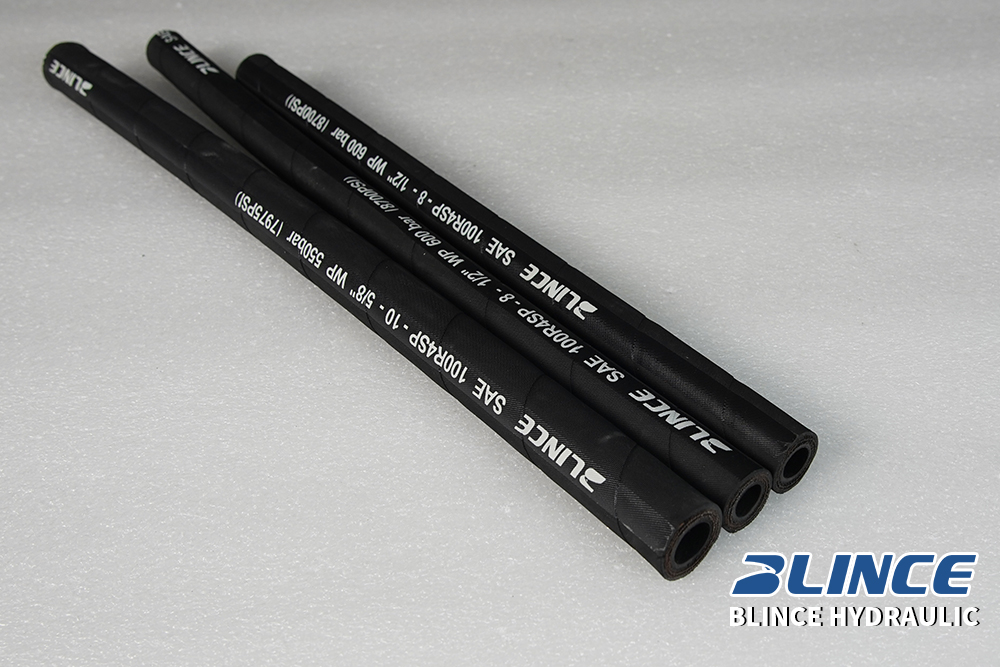
The original hose markings are the starting point for selecting a replacement. Confirm the inside diameter, applicable hose type, fluid, working temperature, working pressure and pressure duty from the machine information. Add any special requirements such as movement frequency, cover abrasion resistance, conductivity or minimum bend radius if they apply. Where the exact values are unknown, include the OEM part number and identify the missing values for confirmation.
Do not infer the hose size from the outside diameter alone. A cover and reinforcement can make two hoses with the same nominal inside diameter look different from the outside. Conversely, two similar-looking covers do not establish equal inside diameter or pressure performance. The BLINCE hydraulic hose types guide can help a buyer put names to the hose families before comparing the exact product information.
Check the completed assembly’s rating with the supplier. Hose and fitting components must belong to an approved combination for the conditions, and the completed assembly is bounded by its applicable component and assembly limits. A pressure number printed on the hose alone cannot establish the finished assembly rating. Ask the supplier to document the hose, fitting series and assembly rating for the offered combination.
If the hose is used in a special application, note it early. A suction line, for example, has service conditions that cannot be judged from a pressure-hose label alone. A line near a hot surface or with an unusual fluid needs documentation that applies to that exposure. When a replacement requires a change in hose construction, check how that affects dimensions, bend limits and fitting compatibility before treating the change as interchangeable.
Use the BLINCE hydraulic hose range to identify the relevant product category. Ask which exact documentation is needed to check the proposed application. The public category does not establish the rating, fittings, stock or availability of a finished assembly. A quote should show what is included so you can tell whether it covers bulk hose, fittings, or a specific finished part.
Check an offer against the machine drawing
Read the offer in the order a technician will use it. Confirm the assembly identity and quantity, then the two end connections, overall length, clocking and hose specification. Compare the drawing with the location of the clamps, guards and moving parts. Verify that any new adapters or fitting shapes will still clear the surrounding parts. If a supplier proposes an equivalent, ask which points are confirmed by the new part’s documentation and which need a machine-side check.
For multiple assemblies, make one row per distinct hose and put its drawing revision on the purchase line. Mark any A and B labels that need to carry through to packaging or the installer’s drawing. Use one clear unit system for all length dimensions even if the connection callouts use mixed standards. On receipt, compare the part to the approved drawing before installation. The old hose can help identify a difference, while the drawing should establish what was ordered.
Follow the equipment and assembly instructions for installation and commissioning. Confirm the hose takes the intended path without twist, that the supports and guards are restored, and that the necessary inspections are done by the qualified technician. If the finished assembly does not sit correctly in the intended route, revisit the drawing before putting it into service. The Gates installation guide gives further context on routing, avoiding twist and checking the completed installation.
Common questions when ordering a replacement hose
Do you measure from fitting to fitting?
Measure the complete assembly between the reference points specified for its two end fittings. For a straight end, a drawing may use a particular end or seating surface. An angled end may use a different reference such as its connection centerline. Include the points on a marked photo or sketch so the supplier can match the convention.
How much length should I add to stop a hydraulic hose pulling tight?
Start by checking where the hose is tight and how the path changes across the machine’s working range. Then confirm the necessary length, fitting angles, minimum bend radius and support positions. An extra length that works with the cylinder extended can snag or pinch when it retracts. Approve the new dimension from the full route.
How do I order a hose with two elbows?
Name both ends, specify each elbow’s angle and include a clocking sketch showing the reference end and the viewing direction. The supplier’s drawing should confirm how the two elbows point relative to each other. Also include the overall length reference points, hose specification and any tight clearances near the connections.
Send one request the supplier can check against a drawing
Include the machine model or assembly part number, the hose marking, the finished length with marked endpoints, the two end descriptions and any clocking sketch. Add one route photo and the tightest clearance or movement condition that affects the fit. Give the application’s pressure, fluid and temperature details from the machine documentation where available. If a required field remains unknown, label it and state which drawing or measurement you can provide next.
Use the BLINCE inquiry page to send the information when you need to check a hose or fitting option. Ask for the assembly drawing and the applicable documented limits before releasing a replacement order. Use that drawing to confirm both connections and check the hose route across the machine’s full working range.