
A hydraulic cylinder pushes or pulls in a straight line. A hydraulic motor turns a shaft. A forklift can use a cylinder to lift its forks, while a conveyor can use a motor to keep its belt moving. Both are hydraulic actuators, the parts that turn the energy carried by oil into movement. You can often tell which one you are looking at by watching what comes directly out of the part.
The difference is easiest to see on a machine that does both jobs. An excavator can use cylinders to move its arm and bucket, and a hydraulic motor to rotate its upper structure or power a track through a gearbox. The operator sees a bucket swing through an arc even when a cylinder is doing the work, because a linkage turns the rod’s push or pull into that swinging motion. Follow the output from the part to the load and the choice starts to make sense.

Start with the motion the part makes
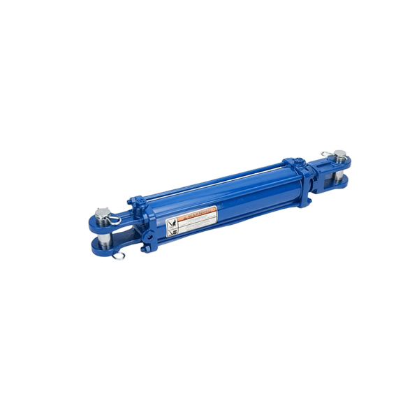
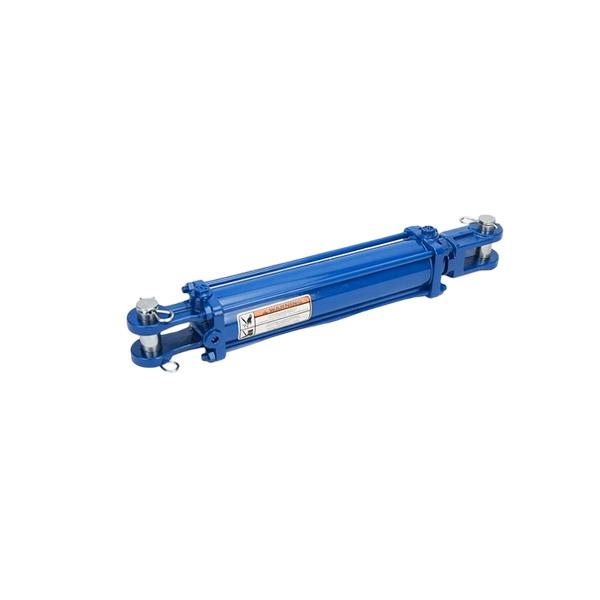
Think of a cylinder as a powered pushrod. In a common design, a metal rod slides out of a tube and then retracts. The end of the rod can move a clamp, raise a lifting mechanism or push against a load. Its travel has a limit, which is called the stroke. A cylinder can repeat the stroke many times as the machine works.
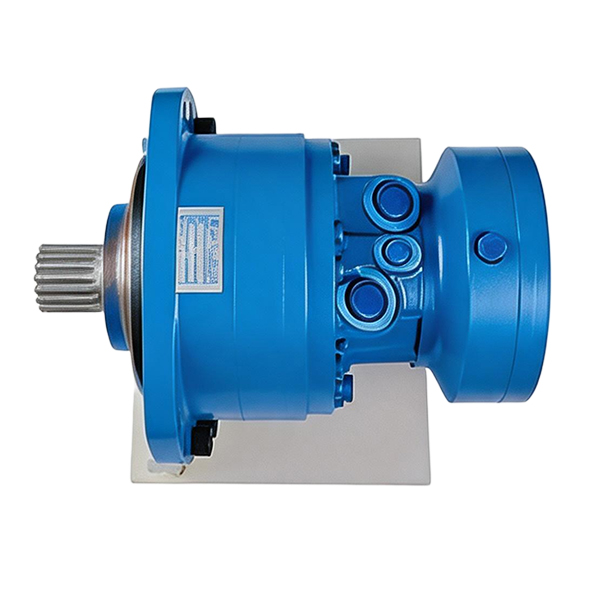
A motor does its work at a shaft. The shaft may drive a wheel, a roller or a gearbox. When the circuit and motor are designed to keep it turning, the shaft can make many revolutions. A hydraulic motor can also turn slowly for a positioning task or reverse when the equipment allows it. The shaft gives you a clue even if a cover hides the final driven part.
| What to observe | Hydraulic cylinder | Hydraulic motor |
|---|---|---|
| Direct motion | A rod or other output moves in a straight line | An output shaft turns |
| Common work | Lift, lower, push, pull or clamp | Drive a belt, fan, auger, drum or wheel |
| Distance or rate | Stroke in millimeters or inches, speed as distance per second | Turns or angle, speed in revolutions per minute |
| Turning or pushing ability | Push or pull force | Torque, meaning turning effort |
| What it usually connects to | A pin, bracket, linkage or load support | A coupling, pulley, hub or gearbox |
HAWE’s hydraulic actuator glossary uses the straight-line and rotating outputs to distinguish the two. It also groups other devices such as slewing drives under actuators. A machine part can therefore fit the actuator label without being either a familiar rod cylinder or a continuously rotating motor.
Follow the oil from the pump to the moving part
The pump sends oil through the circuit. On many machines, an electric motor or engine turns the pump. The pump supplies flow, and pressure rises as the circuit and load resist that flow. A valve directs the oil to a cylinder or motor. The flow helps set its speed, and the pressure helps it move the load.
Picture a simple lift. Moving a lever tells a valve to send oil toward the cylinder. Oil arriving at the correct side of the piston moves it as the load allows. The circuit provides a way for oil to leave the other side when needed. On a conveyor, the valve can instead send oil through a hydraulic motor. Flow through the motor makes the shaft turn, and the shaft moves the belt through the drive roller.
The pump, valve and actuator have different physical jobs. A pump commonly has a shaft that receives motion from its driver. A hydraulic motor has a shaft that delivers motion to its load. A cylinder can also be connected to the same supply and use the energy to produce a stroke. See how these parts fit around the reservoir and controls in the hydraulic power unit overview.
What do flow and pressure mean when you watch the machine?
Flow is how much oil travels through a point each minute. A greater supply to a given actuator generally lets it move faster within its proper operating range. Pressure describes the push the oil applies per unit of area. A load that takes more effort to move generally requires more pressure at the actuator. A fast unloaded stroke can use substantial flow without needing the pressure of a slow loaded stroke.
The same idea applies to things that turn. A motor might spin easily before a conveyor starts carrying product. When the belt is loaded, the motor needs enough turning effort to keep it moving. Its movement also depends on how much oil reaches it. If the machine suddenly slows, an operator can record whether that happened only with material on the belt. The cause may involve the load, the available oil or the drive. The observation helps a technician choose what to test.
The hose count usually offers a weaker clue than the motion. Some cylinders have one working connection and others have two. A motor may have two working connections and, on some designs, a separate drain connection. A valve block fitted to the actuator can make the outside look more complicated still. The service drawing or model plate helps identify the connections when the output is behind a guard.
How a hydraulic cylinder pushes and pulls
Inside a typical cylinder, a piston fits inside the tube and is connected to the rod. Oil pressing on the piston makes it move. If the rod comes out, that is extension. If it slides back into the body, that is retraction. The tube, piston, rod, seals and end connections have to work together under the machine's actual load and mounting alignment.
A floor-mounted press offers an easy picture. The tool travels toward the workpiece as the cylinder moves. The rod reaches the point shown on the machine drawing, and the press can apply force as part of its assigned cycle. A cylinder fitted to a gate can use the same straight motion while the gate itself swings. In this design, the connection point and hinge translate the rod movement into a change in gate angle.
A buyer usually hears three dimensions. The bore is the inside diameter that determines piston size. The rod diameter describes the moving shaft-like part that sticks out. Stroke is the available movement between the two positions. Two cylinders can have the same stroke and look similar in a photo while using different mounting distances when fully closed. The industrial hydraulic cylinder guide expands on how those choices affect a real installation.
Single-acting and double-acting cylinders
A single-acting cylinder uses hydraulic pressure for movement in one direction. A spring, gravity or the weight of the load can return it, depending on the design. Imagine a simple lifting mechanism where the cylinder raises the load and the weight helps lower it through a controlled return. The equipment still needs a safe means of controlling that movement. Its service manual tells you what type is used.
A double-acting cylinder uses oil pressure to drive the piston in both directions. The valve supplies one side of the piston for extension and the other side for retraction. It can drive an implement out, then pull it back. For a familiar product example, the HOB double-acting hydraulic cylinder series shows the style of component a buyer can identify by bore, rod, stroke and mounting details.
For a common cylinder with a single rod, the rod takes up some of the piston area on its own side. Under equal supply flow and similar conditions, that smaller oil space can fill faster during retraction. At the same pressure and with return pressure and losses neglected, the larger area on the opposite side can produce more force. Actual machines can deliberately control the two speeds differently. The rod size explains why the two directions can behave differently even in a healthy system.
What does a stronger cylinder need?
Piston area and the oil pressure acting on it determine the ideal force. Enerpac’s basic hydraulics guide describes the pressure-times-area relationship. This explains why a cylinder with a larger effective area can exert more ideal force at the same pressure. Real installations can lose useful force to friction and opposing pressure, and linkages can change how much reaches the part being moved.
A larger piston needs more oil for the same distance. With the same available flow, it can travel more slowly. Going to a larger cylinder can change speed, physical fit and what the mounting structure has to carry. Choose the dimensions and pressure for the selected machine. Ask the equipment designer to verify changes rather than fitting a larger component and assuming the system can support it.

How a hydraulic motor turns a shaft
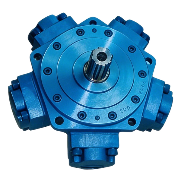
A hydraulic motor uses oil moving through its internal working parts to turn an output shaft. Various designs use gears, pistons or an orbital gear set. The internal shape differs, but the job stays familiar. The shaft delivers rotating motion to whatever is attached to it. Some motors drive the part directly. Others use a coupling, chain or gearbox to transmit the power.
Think of the rollers that pull a conveyor belt. The motor turns a drive roller. The roller moves the belt in a straight line along part of its path. If you look only at the load, the belt seems to move like the rod of a cylinder. Follow the drive back to its source and you find a turning shaft. The hydraulic motor selection guide for a conveyor shows how to connect that shaft motion to a real belt.
Torque describes turning effort. You can think of it as the effort you feel when turning a wrench. A motor may need extra starting torque to get a loaded belt moving, then less torque once the machine is running steadily. Speed is the rate at which the shaft turns, often given in rpm. A gear or chain drive can make the load turn at a different speed from the motor. Ask where a quoted speed or torque is measured so you can compare it to the right part of the machine.
What does motor displacement mean?
Displacement describes how much volume the motor takes in per shaft revolution in the ideal geometric sense. With the same supply of oil, a motor that uses more volume per turn generally turns more slowly, assuming similar losses and the same usable conditions. At the same pressure difference, larger displacement can also provide more ideal torque. The actual startup and running behavior should be taken from the motor's data at the intended conditions.
For example, the BLINCE OMP orbital hydraulic motor series is a catalog family of rotating actuators. A family name helps a technician find drawings and part options. The correct size and shaft still come from the equipment load, available oil and installation. A drive with a guard over the output may also need a photograph of the complete model plate before it can be matched confidently.
Look at machines that use both kinds of motion
A loader or forklift can have several separate movements. Choose the specific one you need to identify. Think about one movement at a time. If you can name what actually moves, in which direction and what it connects to, you can narrow down the component before asking for specs.
A forklift lift and a forklift attachment
The lifting end of a forklift can use a hydraulic cylinder to raise its mast or carriage. The cylinder may move a chain or pulley arrangement as it extends. That mechanism can make the forks travel a different distance from the rod. If your task is identifying the cylinder, measure or obtain the rod stroke from the machine documentation. Fork height is a separate machine dimension.
Now consider a forklift fitted with a powered rotating attachment. The attachment might have a hydraulic rotary drive for turning its load, while cylinders on the same truck still lift or tilt the mast. There are also versions of these machines that use other ways to move or travel. Describe the function and verify the installed drive. “Forklift hydraulic part” is a broad starting point that can describe several unrelated parts on the same machine.
A conveyor belt and its gate
A conveyor belt runs a long way even when the motor that powers it stays fixed in one spot. The motor turns one roller, and the roller carries the belt forward. A cylinder can open a feed gate or push a box from the conveyor onto a different line. The motor may run while the cylinder sits still. Later the cylinder completes one short stroke while the roller continues turning.
Take note of the difference if the machine stops moving. A belt that has stopped can involve its rotating drive, gearbox, shaft, or oil supply. An output gate that no longer reaches its position can involve its cylinder, linkage, controls or mechanical load. Both can feel like a hydraulic fault to the operator. Capturing which action failed, what happened just before it and whether the other actions continued helps the service team approach the right part of the machine.
An excavator arm, swing and travel drive
Watch the exposed rod on an excavator arm from a safe observation point. As the rod extends or retracts, the arm can turn around a pin. The cylinder makes the stroke, while the joints determine the path of the bucket. The cylinder's rod load and movement can differ from the force and motion at the bucket. The machine drawing is therefore useful when comparing a replacement.
Swing and travel are different jobs. A motor and reduction drive can create the rotation needed to turn the upper structure or move a track sprocket. A failed motion can involve the motor, gears, brake, valves or mechanical hardware. If an excavator rotates while its bucket will not curl, write down those two observations separately. They can help a technician decide which component and circuit to inspect.
| Action on the machine | Part to identify first | What you can record without taking it apart |
|---|---|---|
| Lift platform moves up and down | Cylinder and its lifting mechanism | Platform travel, direction, load and whether a linkage sits between it and the rod |
| Belt keeps moving around its rollers | Roller drive and its motor, if hydraulically driven | Belt direction, roller or motor model and when the motion slows |
| Bucket opens or curls through an arc | Cylinder and linkage driving that pivot | Rod motion, movement that fails and original model |
| Upper deck rotates | Swing drive or another turning mechanism | Rotation range, machine model and drive identity |
| Fixture grips a part and releases it | Cylinder or built-in clamp assembly | Direction of powered motion and the amount of travel required |
Recognize motions that can look alike from the outside
A gate may turn through only part of a circle. It can be moved by a cylinder attached to a lever, or by a dedicated rotary actuator, a part that turns through a specified angle. A powered shaft under the gate and a cylinder anchored off to the side represent two ways of getting the same visible result. The service parts diagram shows where the actual output starts. If you can see only the gate, ask for the drawing before assuming how it is driven.
A reciprocating machine can also use rotating power. A shaft with a crank can make a mechanism move back and forth each time it turns. The hydraulic motor could turn the crank continuously while the working head visibly repeats a straight stroke. Identify the moving connector between the load and the hydraulic component. That tells you whether you need a cylinder with a set stroke or a motor and mechanical drive that repeats the motion.
Where does a load stay when the machine stops?
Some cylinders move loads that must remain raised or fixed in place. Some rotating drives also have to hold position. The machine design determines how a load is held after motion stops. It may use a device in the hydraulic circuit, a mechanical brake or lock, another designed support, or a combination. A description such as “the cylinder stopped” or “the motor stopped turning” is an observation about motion. It gives no evidence by itself that equipment is secure for service.
If the machine creeps after it has stopped, record whether the rod slides, the shaft turns or another part slips farther along the linkage. Follow the equipment’s approved service process and keep away from unsupported loads. Several components can influence what the operator sees. The repair team can use the recorded movement and the machine documentation to decide where to investigate.
Which details matter when buying a replacement?
Start with the machine make and model, the part identification and one sentence about what the part moves. A full identification plate and the original drawing are valuable. If it is hard to see the plate, note where the part sits and which function it powers. Ask the maintenance team to obtain photographs and dimensions using the machine’s normal isolation and service procedures. Keep them with the drawing so a buyer can refer to the same part when placing the order.
For a cylinder, give the direction of work, stroke, bore and rod diameter if known. Record the style of mount at each end and the distances that affect fit in the closed and extended positions. Discuss how it is loaded and the speed required in each direction. The BLINCE hydraulic cylinder range gives a starting point for comparing families when the types or mountings differ. Ask for the drawing for the specific offered part before approving it.
For a motor, give the task of the shaft, the required speed and turning effort when known, and any gearbox or drive between the motor and load. Tell the supplier the available pressure and flow from the machine documentation or its measured service data. Confirm shaft shape, flange and ports, direction of rotation and required drain or brake arrangement. State whether the load is supported by the machine or whether a shaft or bearing on the drive has to carry part of it.
| Information to gather | For a cylinder | For a motor |
|---|---|---|
| Job | Lift, clamp, push, pull or position | Turn a roller, wheel, drum or gearbox input |
| How far or how fast | Stroke and time or speed in both relevant directions | Shaft rpm, direction and how often it starts or reverses |
| Load | Required force and whether it acts in extension, retraction or both | Starting and running torque, plus any outside load on the shaft |
| How it attaches | Two mounting ends, fully closed dimensions, rod connection and port details | Mounting face, shaft or hub, ports and any drain or brake |
| Evidence | Original component label, dimensions and machine schematic | Original label, location in the drive, ratio and machine schematic |
Write a sourcing request in one sentence first
“I need the component that pushes this clamp closed and pulls it back” is a better start than “I need a hydraulic part for this machine.” Include the distance and work direction, then attach the drawing or label. For a rotating part, try “I need the drive that turns this roller continuously when the belt is loaded.” That statement helps keep the buyer and supplier on the same component even if the exact code is hard to read.
Once the task is clear, add the working conditions and the model. If you have measurements at the load but not the actuator, keep the two locations distinct. A conveyor belt speed can be converted to roller and shaft speed with the known geometry and transmission. A platform's travel can differ from a cylinder's stroke. A supplier can help interpret those relationships if you include a drawing of the mechanism.
For a BLINCE Hydraulic actuator inquiry, include the machine, the movement, the old part ID or drawing and the details relevant to it. If the main question is still whether a cylinder or motor drives the movement, send a description of the output and its link to the load. The engineer reviewing the drawing can identify what additional measurements are needed.

A few common questions about cylinders and motors
Is a hydraulic actuator the same thing as a hydraulic cylinder?
A hydraulic cylinder is one type of actuator. Hydraulic actuators turn oil power into movement. A cylinder moves a rod directly and a motor turns a shaft directly. When you see “actuator” on a specification, look for the required output motion or the part drawing.
Can a hydraulic motor move something in a straight line?
A motor can drive a roller, lead screw or crank that creates straight movement farther along the mechanism. The motor's own direct output is rotation. If the task and design call for a straight push or pull directly at the load, a cylinder may provide that motion with fewer transmission parts.
Can a hydraulic cylinder cause something to rotate?
Yes. A cylinder can push on a lever connected to a pivot and turn an arm or gate through part of a circle. The cylinder still moves its rod in a straight line. A rotary actuator, a motor or a lever-driven cylinder can all be used to turn a part in appropriate applications. The equipment drawing shows which arrangement is installed.
What is the difference between the hydraulic motor and the pump?
The pump receives motion from a driver and supplies oil flow to the circuit. A hydraulic motor uses oil flow and pressure to deliver turning effort and motion to a load. Both can look similar from the outside. Check which shaft is driven and which shaft drives another machine component, then confirm from the model nameplate or schematic.
Why might a cylinder pull back faster than it pushes out?
On a common cylinder with a rod on one side, there is less space for oil to fill on the rod side. At the same incoming flow, that can make retraction faster. Valves, load and other parts of the circuit can change actual travel speed. The equipment may also intentionally limit one stroke. If the difference is new or the motion changes under load, record when it happens for the service team.
Can a cylinder and motor work from the same power supply?
A hydraulic power unit can supply both if it and the control circuit are designed for their needs. A valve can direct supply to a cylinder, a motor, or different branches at the same time. Simultaneous movement can affect how much flow is available to each. Verify how the machine is designed to operate before selecting the pump, actuators or controls.