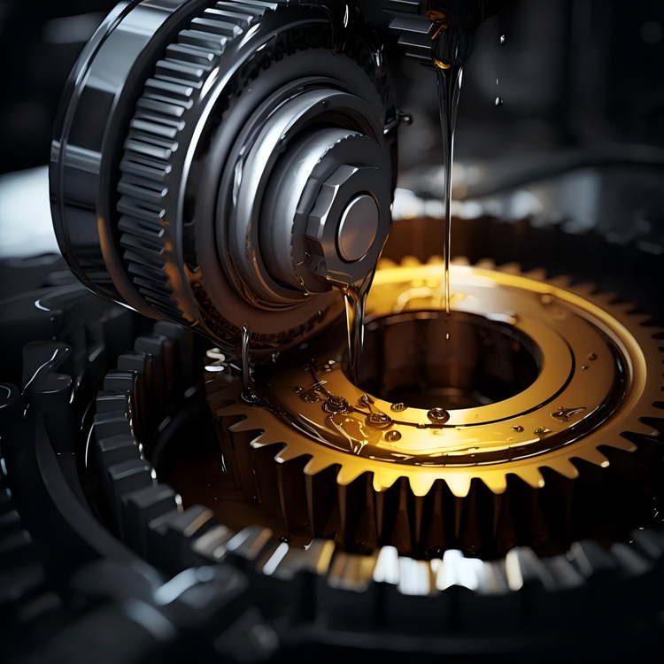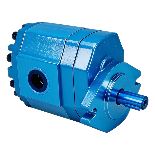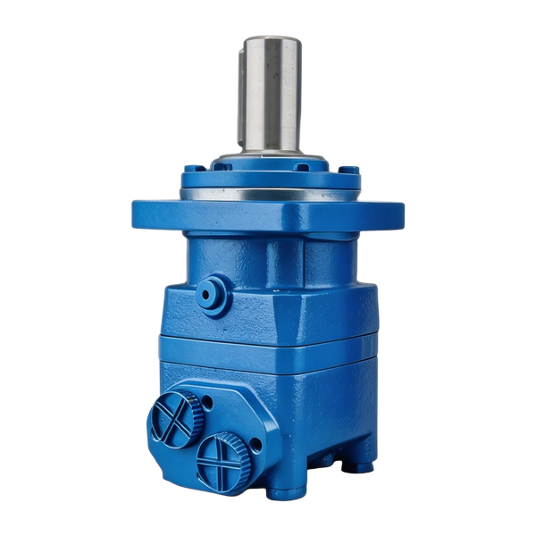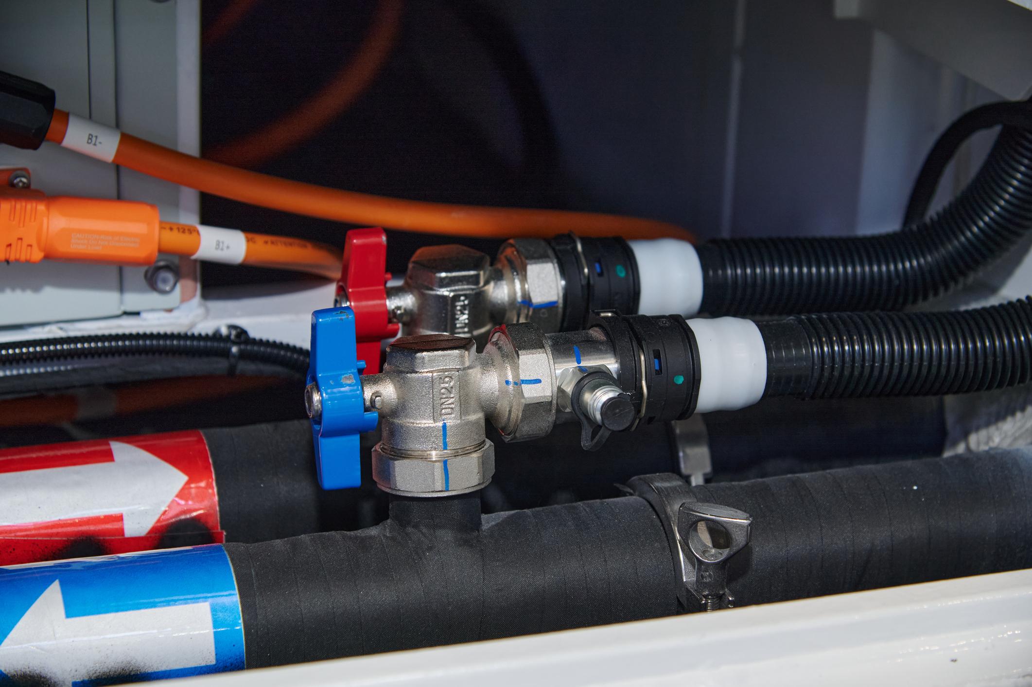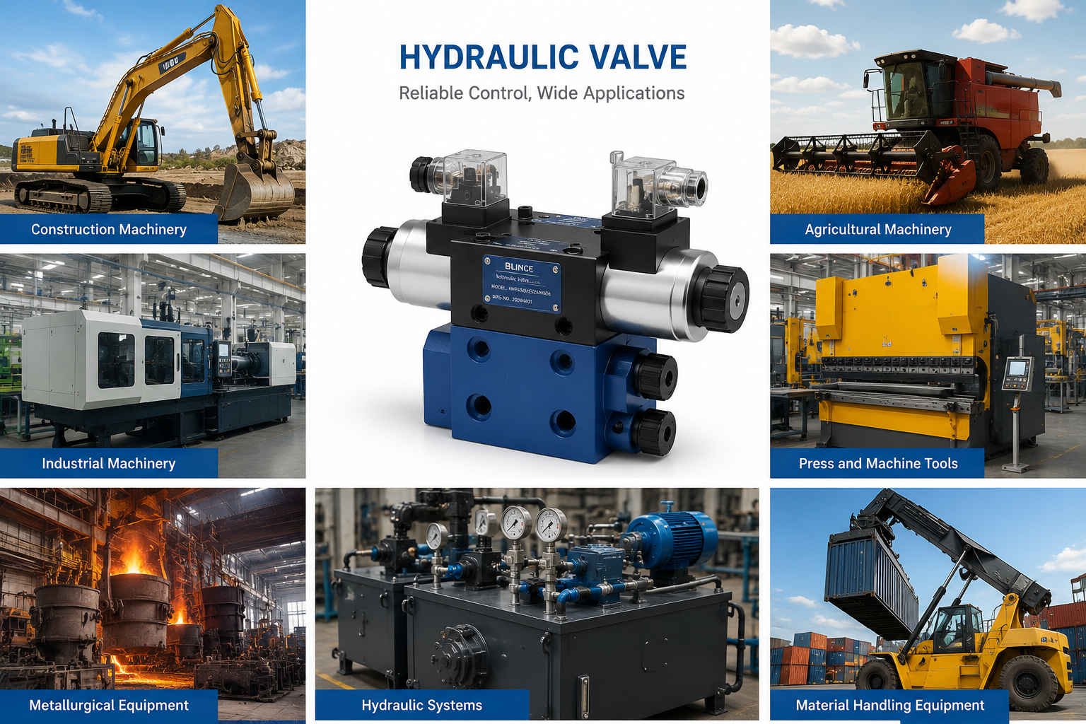

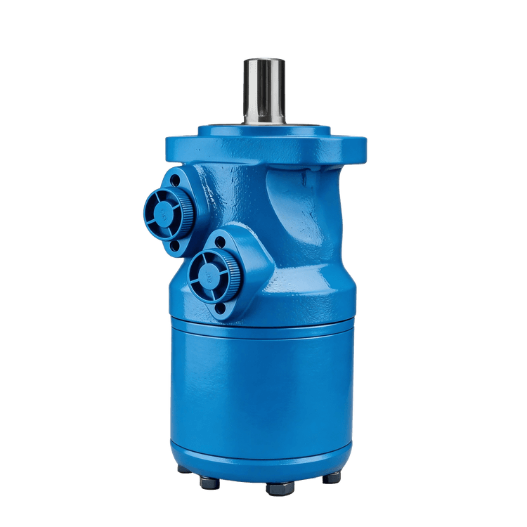
A hydraulic swing motor supplies the rotation used to turn an excavator's upper structure. The complete drive may also contain reduction gears, a pinion, a parking brake and valves. A buyer ordering “one swing motor” needs to name which of these parts will arrive and which will remain in the machine.
Consider two hypothetical quotations. Offer A supplies only the hydraulic section for the retained gearbox. Offer B includes the motor and reduction gearbox. Their displacement entries could agree, yet the installer would receive different parts. Label the supplied boundary on the old unit's photograph before comparing those prices.
The duty review then follows rotation from the motor shaft to the upper structure, covering acceleration and the stop as well as working speed. The example below uses illustrative inputs throughout. They were chosen for explanation and do not describe a BLINCE unit or a measured excavator.
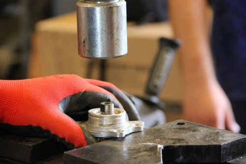
Mark the parts included in the requested swing drive
Use the installed assembly sketch to mark a supply boundary. For a motor-only order, that boundary falls at the connection to the retained gearbox. For an assembled drive, it extends to the machine mounting and the output engagement. The table below can be used to annotate that sketch; a blank against an included function means the offer still needs clarification.
| Part or function | Identification to request | Why it affects the supply scope |
|---|---|---|
| Hydraulic motor | Complete model, displacement, port arrangement and drawing | Defines the hydraulic input and motor-side mechanical interface |
| Reduction gearbox | Assembly code, ratio, lubrication and interface drawing | Changes the relationship between motor speed and output speed |
| Output pinion | Tooth geometry, dimensions and matching ring-gear information | Establishes the final mechanical engagement |
| Parking brake | Brake type, rated function, release arrangement and code | Determines holding behavior and its control requirements |
| Valve block | Circuit symbol, full option code and settings documentation | Defines protection, replenishment and motion-control functions |
| Complete assembly | Assembly number and bill of material | Confirms which of the above are included in the quotation |
In the hypothetical motor-only offer, the old gearbox and pinion remain part of the working drive. Their condition and interfaces still matter, although their price is absent from the offer. An assembly number or itemized bill of material makes that scope easier to verify than the words “complete motor.”
Keep one wider photograph with the readable tag close-ups. It should show where each tagged component sits and where its hoses run. If a plate belongs to the gearbox, label it as such on the sketch. Otherwise a perfectly transcribed code can send the supplier searching for the wrong component.
For basic terminology, BLINCE's existing travel motor versus slew motor guide distinguishes the machine functions. The task here is narrower: defining a particular swing-drive replacement and the evidence needed to assess it.
Read the motor architecture from documentation
Published product descriptions show why the scope needs spelling out. Kawasaki's M5X description identifies a fixed-displacement swash-plate axial-piston motor for swing service, with a built-in parking brake. On an M5X inquiry, that manufacturer description provides a starting definition of the hydraulic unit. The full code and drawing are still needed to identify the ordered configuration.
The Bonfiglioli 700TK hydraulic slew-drive page describes an integrated package with axial-piston motors and lists ratios, an output pinion and parking-brake options. Reading the two descriptions as assembly information is more useful than putting them into a single row labeled “hydraulic motor.” Neither is a specification for a BLINCE product.
For BLINCE inquiries, the hydraulic slewer motor category and ZMQ series product page identify listed products. Ask for the proposed configuration's assembly drawing before comparing it with the removed drive. No specific excavator interchangeability or matching gearbox, valve and brake package is established here.
Even a comparison confined to axial-piston motors has several open rows: interfaces, valving, drain requirements and operating limits. Moving to another motor architecture can broaden that review to the machine circuit itself. Record such a proposal as a design change requiring approval, rather than allowing a similar external shape to make it look like a routine substitution.
Do not open an installed motor merely to identify its internals. Its full code, the machine parts information and the manufacturer's assembly drawing are better starting evidence. If internal inspection becomes necessary, the machine and component service procedures should determine who performs it and how.
Relate motor speed to upper-structure speed
Follow the rotational path from the hydraulic shaft, through the reduction gears and pinion, to the upper structure. There can be more than one reduction in that path. The ratio needed in the calculations below covers all of them:
i = motor shaft speed / upper-structure speed
With 80:1 total reduction, 8 rpm at the upper structure requires 640 rpm at the motor. A gearbox sheet might instead report only its internal ratio. In that case, the remaining pinion-to-ring-gear relationship must be brought into the calculation before the 8 rpm requirement can be translated to a motor operating point.
Use the same locations to label torque. A row saying “motor shaft” can be compared with a motor curve. A row saying “about the swing axis” describes the machine-side demand. The gearbox output lies between them. Leaving off these labels can make two incompatible numbers look like a generous torque margin.
For a simplified forward-driving estimate:
Tout = Tmotor × i × ηg
For this relation, ηg represents efficiency along the full mechanical path while the motor drives the load. Use transmission evidence for the actual duty when making a final selection. During a stop the rotating machine can drive back into the transmission; the forward-running assumption is not a validated model of that reverse energy path.
| Supplied number | Clarification before using it |
|---|---|
| “Swing speed: 8 rpm” | Is this the upper structure, output pinion or hydraulic motor shaft? |
| “Ratio: 20” | Does it include the final pinion-to-ring-gear reduction? |
| “Torque: 10,000 N·m” | At which shaft or machine axis, and for what duty? |
| “Motor displacement: 100 cc” | Is this the hydraulic unit's geometric displacement or an equivalent assembly value? |
| “Maximum pressure” | At which port, for how long and under which operating restrictions? |
An engineer can now mark the location of an offered figure directly on the drive sketch. A large torque at one location cannot be used to fill a missing rating at another without the intervening ratio and the applicable transmission data.
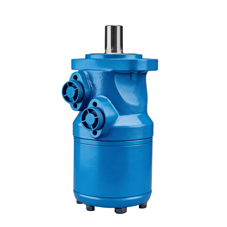
Estimate acceleration from rotating inertia
A swing drive has to accelerate the mass distributed around the swing axis. Machine weight alone does not specify that task. The position of the boom, attachment, payload and other rotating parts changes the mass moment of inertia. External resisting or assisting moments also depend on the working condition.
For a simplified rigid-body calculation with constant acceleration:
Taccel = J × α
The units are kg·m² for J and rad/s² for α. Convert a speed n in rpm to rad/s by multiplying by 2π/60 before calculating acceleration. A resisting moment is then added with its direction defined. This compact model holds inertia fixed; a machine assessment may also need changing geometry, friction and the actual command profile.
Take a hypothetical duty with these assumptions:
| Assumed input | Value | Scope of the assumption |
|---|---|---|
| Rotating inertia about the swing axis | 50,000 kg·m² | Fixed for this one example, not inferred from machine weight |
| Target upper-structure speed | 8 rpm | Motion about the machine swing axis |
| Acceleration time from rest | 2.5 seconds | Constant acceleration assumed |
| Resisting torque at the swing axis | 1,500 N·m | Constant and opposing the motion |
| Total mechanical reduction | 80:1 | Includes the complete path to the upper structure |
| Assumed forward mechanical efficiency | 0.90 | An illustrative value, requiring actual transmission data |
At 8 rpm, angular velocity is about 0.838 rad/s. Reaching it in 2.5 seconds gives α of about 0.335 rad/s². The inertial torque is then 50,000 × 0.3351, or approximately 16,755 N·m. Adding the assumed 1,500 N·m resistance gives about 18,255 N·m at the swing axis during this idealized acceleration.
Dividing 18,255 by the assumed 80 × 0.90 gives roughly 253.5 N·m at the motor shaft. Record that result under “simplified forward acceleration.” Actual breakaway behavior, starting efficiency and transient pressure are still outside this calculation, and the proposed gearbox has not been rated by it.
Changing the hypothetical acceleration from 2.5 seconds to 1.25 seconds doubles the inertial contribution. It leaves the assumed 1,500 N·m resisting contribution unchanged. Thus two requests that both specify 8 rpm can impose different acceleration demands. The requested time to reach speed belongs in the duty description alongside the final speed.
The engineer needs the machine's permitted motion profile and load cases, not just an operator's impression that the old drive felt slow. Those requirements let the supplier compare running, acceleration and transient duties separately.
Match flow and differential pressure at the motor
Having translated the machine duty to the hydraulic shaft, the next calculation concerns supply. The general motor relationships on printed page 2 of Parker's F12 service manual can be written in the following units:
Q = D × n / (1,000 × ηv)
T = D × Δp × ηhm / (20π)
In these equations, enter Q in L/min, D in cm³/rev and n in rpm. Enter Δp as the inlet-to-outlet pressure difference in bar. Both efficiency inputs must refer to the operating condition being assessed. The torque conversion uses 20π here; its rounded catalog form is often written as 63.
Continue the constructed example with a trial displacement of 100 cm³/rev. Assume running volumetric efficiency of 0.92 and hydro-mechanical efficiency of 0.90 for an initial screening calculation. These are invented example inputs, not published efficiencies for a selected unit.
The trial 100 cm³/rev unit at 640 rpm gives Q = 100 × 640 / (1,000 × 0.92), approximately 69.6 L/min. Rearranging the torque expression for the 253.5 N·m screening requirement gives approximately 177 bar differential pressure. These two numbers now occupy the same hypothetical operating-point row, with their assumptions attached.
Compare that row with the supply under the intended machine state. A 50 L/min supply would fall short of the calculated 640 rpm point at the assumed efficiency. Similarly, an upstream pressure of 177 bar with 20 bar at the outlet leaves only 157 bar before allowing for any additional loss between the upstream gauge and motor inlet. Gauge location should be part of the recorded value.
Add a separate supply row for any required combined movement, such as swinging while a boom function operates. Its available flow may differ from swing alone because the pump and valve arrangement has another demand to serve. The machine's published maximum pump flow is background information until the circuit establishes what reaches this particular function.
The trial calculations leave starting behavior, internal leakage, braking, port pressures and efficiency maps unresolved. Use actual manufacturer data for the final duty review. Where a catalog lists theoretical torque, identify it as theoretical rather than treating it as measured available shaft torque.
Give deceleration and parking separate requirements
Once the upper structure is moving, stopping it involves kinetic energy. For the same simplified fixed-inertia example:
E = ½Jω²
For the example, E = 0.5 × 50,000 × (2π × 8 / 60)², approximately 17.5 kJ. Dividing by the assumed 2.5-second stopping time gives a mean of 7.02 kW. Keep this as a kinetic-energy entry in the calculation record until the machine's energy path has been established.
Where does that energy go in the actual machine? The answer comes from the deceleration circuit and mechanical path. It may involve dissipation through hydraulic pressure drops or, in another architecture, some recovery. External work and losses must be added to the balance where applicable. None of these paths can be assumed merely because a replacement arrives with a parking brake attached.
The brake sheet needs two different questions answered: what holds the stationary structure, and what controls deceleration before it becomes stationary? A catalog phrase such as “hydraulically released” does not fill the dynamic-duty entry. That entry requires the brake manufacturer's actual permission for engagement during motion and its applicable limits.
Kawasaki lists motor, brake-torque and brake-release information in its M2X/M5X catalog. Keep those as separate entries when reviewing the packaged unit against the machine requirements.
| Requirement | Evidence needed from the actual drive |
|---|---|
| Bring normal swing motion to rest | Approved deceleration behavior, energy path and duty limits |
| Hold after stopping | Parking-brake holding requirement and engagement conditions |
| Release for commanded movement | Release-pressure requirement, supply path and control timing |
| Respond to a loss of pressure or power | Machine-specific approved behavior and validation criteria |
| Perform repeated work cycles | Thermal duty and permitted frequency under the relevant loads |
Relief settings and brake timing belong to the approved machine adjustment or design procedure. Shortening the requested stop changes the duty the circuit and structure must handle. Bypassing the brake-release control to get a shaft turning would remove part of the system being evaluated, so it cannot establish acceptance of a replacement.
Trace the valves and drain routes on the actual circuit
A swing-drive valve block can contain several functions. Relief or anti-shock arrangements limit pressure under defined conditions. Make-up routes can supply a low-pressure side during motion or deceleration. Other arrangements influence swing-back, brake release or stopping behavior. The functions and their settings vary with the assembly.
Use the installed schematic to tag each connection. Trace any unidentified small hose to both ends before deciding whether it carries drain oil, brake-release supply or another control signal. The resulting connection record should pair every retained hose with its function and its destination on the replacement drawing.
For a drain connection, follow the path all the way to its permitted destination. A shared return, filter or small fitting can contribute pressure that was absent from a bare-motor comparison. Record the proposed unit's leakage and housing-pressure requirements against that path at the relevant oil conditions, separately from working-port differential pressure.
On the make-up connection, mark both the oil source and the states in which that source is available. Following a stop command, the moving structure can still drive the shaft while the supply command changes. Trace the lower-pressure-side filling route for that interval on the schematic, using the approved circuit requirements.
A replacement relief cartridge needs more than a dimensional cavity match. Keep its identification, circuit function and approved setting in the comparison. A change in response or routing can affect a stop even where the threaded cartridge fits. Setting changes require approved commissioning instructions for that machine.
Once the connection comparison is resolved, retain a single marked drawing showing pressure, drain and brake-release assignments. This becomes part of the installation packet. It is much clearer than leaving the agreed hose destinations scattered across quotation notes and later correspondence.
Use a symptom to choose an investigation
Slow swing, rough stopping and drift after stopping are observations. They can direct a test, but none proves that the hydraulic motor is the failed component. The gearbox, brake, control system, supply and external machine load may also be involved.
| Observed condition | A useful distinction to establish | Evidence that helps |
|---|---|---|
| Slow in both directions | Insufficient supply versus motor, brake or mechanical resistance | Machine state, flow and pressure at identified points, relevant service checks |
| Different speed by direction | Different load, control path or internal behavior | Comparable load conditions and direction-specific observations |
| Delayed movement after command | Control response, brake release or drive response | Command sequence, approved timing information and documented release checks |
| Sharp stopping or repeated swing-back | Deceleration behavior versus mechanical play or control behavior | Approved motion profile, circuit details and mechanical inspection |
| Movement after neutral | Continued motion, backlash settling, hydraulic leakage or holding fault | Defined time interval, machine position and brake/control state |
| Abnormal heat or noise | Hydraulic loss, brake drag, lubrication or mechanical damage | Location, temperature, oil condition and load history |
Any intrusive investigation starts with the machine's service procedure: secure the upper structure and attachments, control stored energy and keep people outside the movement envelope. Qualified personnel must plan the rated instrumentation and the specified test arrangement. The symptom table helps define a question for that work; it does not authorize a live disconnection or an improvised motion test.
“Drifts” is particularly ambiguous in a service request. Is it a brief movement as backlash settles, rotation continuing after neutral, or loss of holding in a stated machine position? Add elapsed time and command state to the observation. The engineer can then distinguish questions about stopping, play and holding instead of treating all three as one motor-leakage complaint.
Recent repair history can narrow the investigation. In a hypothetical service note saying “the symptom began after hose replacement,” the changed connection is a specific item to review. A gradual symptom with no recent intervention supplies different evidence. Keep those notes and any mechanical findings with the removed-unit identification instead of reducing the whole history to “motor faulty.”
Compare interfaces that a flange photograph cannot show
Offer A retains the gearbox, so compare its motor-side drawing with the proposed motor from one reference face. In a hypothetical dimensional check, the shaft tip lies 30 mm from that face and the mating engagement begins 5 mm behind it. Subtraction leaves 30 − 5 = 25 mm reaching the engagement region. Usable spline lengths, end clearances and the permitted engagement must then be resolved from the matched drawings before fit can be accepted. These assumed dimensions are included only to explain the drawing comparison.
Offer B replaces the assembly. Its comparison starts at the machine mounting and pinion engagement instead. The following drawing rows apply to different boundaries:
| Drawing row | Offer A: retain the gearbox | Offer B: complete drive |
|---|---|---|
| Primary reference face | Motor connection on the existing gearbox | Drive mounting on the machine |
| Centering and fastening | Pilot, face and bolt details of the motor interface | Machine pilot, mounting face and fasteners |
| Torque-transfer interface | Shaft or spline, usable engagement and end clearance | Output pinion position and matched ring-gear geometry |
| Space around the assembly | Motor envelope, hose access and removal clearance | Complete drive envelope and access to all connections |
For the pinion comparison, tooth count is one entry among module or pitch, tooth form, pressure angle and face width. Retain the matched ring-gear drawing and specified engagement conditions. A common tooth count by itself leaves too many of those rows unanswered.
A torque rating also needs a named duty. Keep stall torque, continuous operation and permitted transient loading in separate entries where the gearbox manufacturer distinguishes them. Frequent reversals introduce a different service history from a single brief static loading. The machine's cycle must be assessed against the applicable gearbox and bearing information.
Mark lubricant compartments on the assembly drawing. Where the motor uses hydraulic oil and the gear housing uses another lubricant, assign each specification and fill instruction to the corresponding compartment. Carry the proposed unit's service instructions into the installation record.
Any changed ratio, pinion, brake or hydraulic control gets a separate change entry and the engineering approval it needs. Bolting the package into the machine cannot close such an entry. This also lets procurement distinguish an accepted direct replacement from a proposal that still depends on a machine design review.
Separate a repair quotation from a complete replacement proposal
An itemized repair scope should connect proposed work to inspection findings. “Replace hydraulic rotating group” leaves the condition of a retained gearbox and brake-related parts as separate questions. The applicable service inspection must answer them. Rebuilding the assembled drive has a wider scope and should identify the additional inspected and supplied items explicitly.
For a new-unit offer, match the claim to the old assembly and machine serial information. A catalog's long machine-brand list is a discovery aid, not evidence for this serial range. Revisions and options can change the drive within one named machine model, so retain the drawing or part-number basis for the claimed fit.
A scope comparison for the two hypothetical offers could use the following entries. These describe purchasing boundaries, not approval of any component:
| Quotation entry | Motor-only offer A | Assembled-drive offer B |
|---|---|---|
| Hydraulic unit | Proposed code and options listed | Motor code within the assembly listed |
| Reduction gearbox and pinion | Retained-unit condition and interface review remains open | Supplied assembly identifiers and machine interface required |
| Brake and valve functions | Identify supplied versus retained functions individually | Identify which functions the assembly includes |
| Installation changes | List any changed adapters, hoses or controls | List any machine-side changes needed |
| Technical documents | Motor duty and mating-interface evidence | Assembly definition, duty and machine-connection evidence |
Commercial terms can then be compared against a known list of supplied parts. Keep unresolved technical entries open even when price and delivery have been agreed in a quotation.
Ask for the documents that close those open rows. For a motor-only purchase, that may be the hydraulic configuration and motor-to-gearbox drawing. For the complete drive, the bill of material and machine engagement drawing become central. A general certificate packet cannot fill an unknown assembly number or brake-control arrangement.
Agree on acceptance before the drive arrives
Write down how the replacement will be judged under the machine manufacturer's commissioning procedure. Include correct direction, commanded movement, approved speed, stopping behavior, holding function and operation with the specified simultaneous functions. Define the machine configuration and load conditions for those checks.
Name the measurement point and machine state in the acceptance record. Separate the unloaded warm run from loaded cycling and holding checks. For pressure, retain a transient trace with its duration as well as the evidence for sustained operation, so a brief spike is not entered as continuous duty.
Where the machine has a required fail-safe response, acceptance must include the specified validation by qualified personnel. The presence of a parking brake on a catalog page does not prove that the installed machine meets that response. The integration and control behavior are part of the assessment.
An inquiry through BLINCE's official contact page can begin with the marked supply boundary, readable tags and machine serial information. Attach the hydraulic and interface drawings needed for that boundary. The duty description should add swing speed, acceleration and stopping requirements, load conditions and any documented fault findings, with estimates clearly identified.
Request a named proposed configuration and a comparison with the retained or replaced assembly. Where a critical row remains unknown, record the missing document or the reason the proposal cannot be accepted. That is a useful result of a technical inquiry, and it belongs beside the commercial offer before installation is authorized.