
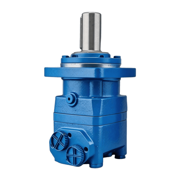
Specify pulley torque and speed together when choosing a conveyor hydraulic motor. Check the supply at that load, followed by loaded starting, shaft support and stopping. The proposed configuration needs evidence for the complete duty.
The worked example below follows two trial displacements through one belt requirement. Available pressure rules out one trial; available flow prevents the other from reaching the target speed. Keeping those results on the same worksheet gives the supplier a defined problem to resolve.
The discussion below concerns belt conveyors. Other conveyor types need their own load assessment. The numerical examples use invented design inputs, separate from BLINCE ratings and reported project results. They explain the review without authorizing changes to machine pressure settings.
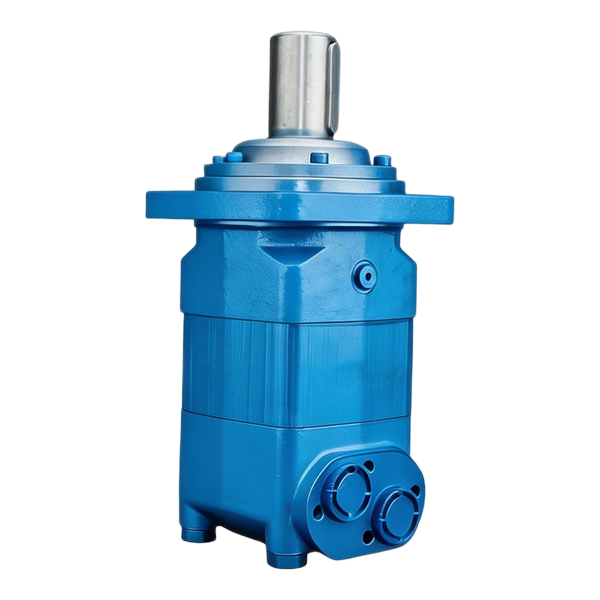
Define the conveyor duty before choosing a motor family
A payload capacity is insufficient to calculate the drive. The layout also needs the belt support, drive position, inclination and required movement, with the material being carried identified. A folding or movable conveyor may have more than one intended working arrangement.
Include empty movement, production and any intended loaded restart in the duty sheet. On a continuous-running machine, an upstream stop can leave material on the belt. The required restart condition then needs to reflect that retained load.
Match each load state to its supply condition. On a mobile screening plant, several functions may share the pump. Its advertised maximum flow alone leaves the conveyor's allocation during simultaneous operation unknown.
| Duty field | Information to record | Why the drive review needs it |
|---|---|---|
| Conveyor arrangement | Belt type, length, inclination, support and drive position | Establishes the mechanical assessment to use |
| Required movement | Minimum, normal and highest belt speed; required directions | Defines the output-speed range |
| Load states | Empty, normal, maximum intended load and loaded restart | Prevents one running condition from standing for the whole duty |
| Operating sequence | Running periods, stops, starts and simultaneous functions | Connects the motor duty to the hydraulic supply |
| Stopped state | Allowed movement and required load support | Defines holding and stopping requirements |
| Installation | Pulley, transmission, mounting, space and shaft support | Defines the interface the motor must fit |
Keep the load assessment traceable. A conveyor designer may supply the drive force or pulley torque directly. Alternatively, a validated calculation or qualified measurement may establish it. Record which route supplied the number and the operating condition it represents. A total material mass without resistance and geometry is insufficient for that purpose.
An existing BLINCE application page, such as Mobile Screening Plants, provides useful equipment context. It does not establish a motor rating for every conveyor on that machine. The individual drive still needs its own operating requirement and selected configuration.
Translate belt movement into a defined drive interface
Belt speed and motor RPM use different units. The relationship passes through the effective drive-pulley diameter and any transmission. With no slip at the drive and an effective pulley diameter d in metres, pulley speed is:
Pulley speed n, rpm = 60 × belt speed v, m/s ÷ (π × d, m)
The worksheet below uses an assumed effective diameter of 0.20 m with no drive slip. Its RPM calculation describes movement only; traction remains a mechanical check.
Where the conveyor designer supplies effective tangential drive force F in newtons at that pulley, the corresponding torque is:
Pulley torque T, N·m = F × d ÷ 2
F is the net effective tangential drive requirement. Shaft-load assessment needs the actual belt tensions and geometry as separate inputs; it cannot take F as the complete bearing load.
| Interface | Value in the hypothetical normal-running example |
|---|---|
| Belt | 0.50 m/s |
| Effective drive-pulley diameter | 0.20 m |
| Pulley | 60 × 0.50 ÷ (π × 0.20) ≈ 47.75 rpm |
| Effective tangential drive force | 2,000 N, assumed from the conveyor load assessment |
| Required pulley torque | 2,000 × 0.20 ÷ 2 = 200 N·m |
| Direct-coupled motor | Same nominal speed and torque before connection losses are assessed |
A proposal with a reduction stage needs its own motor-side calculation. Compare both proposals at the same conveyor interface first; then trace backward through their transmissions. This prevents output torque after a reducer being mistaken for a comparable bare-motor rating.
Retain the process calculation that supplied the belt-speed target. It should establish the required throughput or product spacing for the intended loading, rather than inferring tonnes per hour directly from a motor-speed figure.
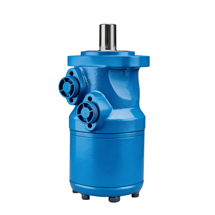
Check pressure and flow together in one sizing example
The following desk example shows why displacement cannot be selected from torque or speed in isolation. It uses assumed efficiencies for preliminary running calculations; actual selection needs the offered motor's operating data. In particular, these running assumptions do not establish starting torque.
Keep the example pulley and add a heavy steady-running condition. The additional assumptions are:
| Example input | Assigned value |
|---|---|
| Heavy-state effective drive force | 3,500 N |
| Heavy-state pulley torque | 3,500 × 0.20 ÷ 2 = 350 N·m |
| Required direct-drive speed | Approximately 47.75 rpm |
| Available supply during that state | 9 L/min and 150 bar across the motor |
| Running efficiencies used for the screen | ηv = 0.90; ηhm = 0.85 |
| Trial geometric displacements | 160 and 200 cm³/rev, without identifying products |
The efficiencies are assumptions for this calculation, not typical BLINCE values. Actual motor data may change the screen and is essential for the final review.
For the motor-side running screen:
Flow Q, L/min = n × D ÷ (1,000 × ηv)
Torque T, N·m = Δp × D × ηhm ÷ (20π)
n denotes motor RPM, D is in cm³/rev and Δp is the inlet-to-outlet pressure difference in bar. The supply assumption refers to that difference at the motor. The pressure column below comes from rearranging the torque equation for the required 350 N·m.
| Running-screen result | Trial 160 cm³/rev | Trial 200 cm³/rev |
|---|---|---|
| Flow for approximately 47.75 rpm, with assumed ηv | 8.49 L/min | 10.61 L/min |
| Pressure difference for 350 N·m, with assumed ηhm | 161.7 bar | 129.4 bar |
| Calculated torque at the assumed 150 bar limit | 324.7 N·m | 405.8 N·m |
| Result against 9 L/min and 150 bar in this example | Flow fits; heavy-running torque does not | Torque screen fits; target-speed flow does not |
The 160 trial is not rescued by having enough flow: its calculated heavy-running pressure requirement exceeds the assumed available difference. The 200 trial solves that running-torque screen but needs more flow than the example permits at the target speed. At 9 L/min and the assumed ηv, it reaches 40.5 rpm, corresponding to about 0.424 m/s belt speed under the no-slip assumption.
Neither trial meets the complete direct-drive requirement. Keep the supply conflict open for the design review: another displacement or drive ratio may be investigated, or the supply or agreed process requirement may need revision. Reduced belt speed and increased pressure are changes to assess, not automatic remedies.
Any next candidate still needs its actual pressure-speed envelope, shaft-load and thermal checks. The running screen has not addressed starting or stopping.
Treat loaded starting as a separate selection condition
The running worksheet leaves loaded starting open. A stopped belt may need to overcome resistance before any steady motion exists. The drive may also have to accelerate moving parts and material within an agreed time. A single running-torque value cannot describe that whole event.
Danfoss treats minimum starting torque separately from running performance in General, Orbital Motors, December 2021. The relevant lesson for this review is to obtain starting data for the offered motor. The named manufacturer's values do not specify a BLINCE motor, and the earlier running-efficiency assumption supplies no starting guarantee.
The start requirement needs its own load profile, available pressure difference, acceleration target and start frequency. Attach the conveyor designer's assessment where available. An unknown start requirement remains an open input; an arbitrary multiplier on running torque would conceal it.
| Operating event | Requirement to establish | Motor or system evidence needed |
|---|---|---|
| Empty start | Resistance and acceleration of the unloaded assembly | Applicable starting and acceleration capability |
| Loaded restart | Intended material load and resistance after a stop | Starting data at the available hydraulic conditions |
| Normal run | Sustained torque, speed and duration | Applicable continuous operating envelope |
| Heavy running | Higher intended load and how long it lasts | Rating and thermal suitability for that duration |
| Jam or unintended blockage | Approved machine response | Protection strategy and qualified recovery procedure |
A loaded-start assessment covers the intended load, leaving fault recovery to the machine's approved procedure. Jam clearing needs its own isolation and removal method. If reversal forms part of an approved operating sequence, the mechanism, circuit and surrounding process all need to support it.
The loading sequence can help the design. A machine intended to start empty and receive material afterwards should have that sequence reflected in its controls and operating instructions. If loaded restart is necessary in service, it needs to remain in the engineering review even if empty-start demonstrations are easier to arrange.
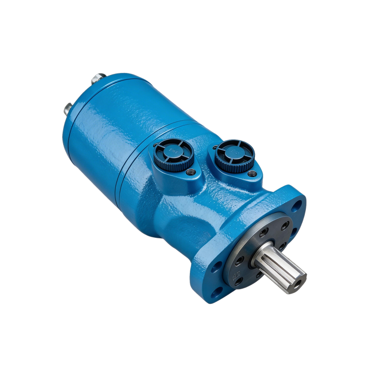
Compare direct drive with a motor and reduction gear
Direct coupling puts the motor near the pulley's speed and torque requirement. A reduction stage lets the motor run faster while the pulley runs more slowly. It adds its own efficiency, mounting and rating conditions. The selection is between complete drive arrangements, not two unrelated catalogue maxima.
For a second arrangement of the same example, assign a 3:1 reduction and 0.95 transmission efficiency at the assessed running condition. These invented inputs produce the following motor-side requirement:
| Conversion | Result |
|---|---|
| Motor speed | 47.7465 × 3 ≈ 143.24 rpm |
| Motor torque for 350 N·m at the pulley | 350 ÷ (3 × 0.95) ≈ 122.8 N·m |
An actual reducer proposal needs its own ratio, losses and duty data in place of these assumptions.
| Comparison item | Direct arrangement | Arrangement with reduction |
|---|---|---|
| Speed reference | Motor near pulley speed | Motor speed determined by the actual ratio |
| Torque reference | Motor connected near the pulley requirement | Convert output requirement through ratio and losses |
| Mechanical scope | Motor, coupling and required support | Motor, reducer, connections and required support |
| Rating review | Exact motor and installed loads | Both motor and transmission at the actual duty |
| Service information | Motor drawing and assembly arrangement | Motor and reducer drawings, maintenance and removal access |
A reduction stage changes speed and torque together. In the heavy-running example, the required mechanical power at the belt remains 3,500 N × 0.50 m/s ÷ 1,000 = 1.75 kW. Upstream losses increase the input needed to deliver it. Evaluate a revised ratio using the actual motor, transmission and supply data.
The installation may make one arrangement more practical. Direct mounting could reduce component count where a suitable motor and support exist. A reducer could suit a higher motor-speed operating point but require additional space or maintenance access. Avoid claiming a universal cost or efficiency advantage without the actual proposals.
Keep the output-pulley requirement in both quotation packages. It gives the reviewer a common reference for torque, speed, acceleration, stopped behaviour and acceptance. A quoted motor torque without the transmission context cannot establish performance at the belt.
Review belt traction and bearing load with the mechanical design
The mechanical layout has two jobs to resolve after the torque calculation: transferring effort into the belt and supporting the assembly. The motor's output figure settles neither the traction arrangement nor the external loads.
For friction-driven fabric belts, Habasit's Engineering Guide, Media No. 6039 relates power transmission to contact, friction and tension. It describes the additional shaft/bearing load from increasing tension. Apply that explanation within the document's fabric-belt scope; a particular bulk-material conveyor needs its own approved belt and mechanical design.
For the motor review, identify how the pulley is supported. Is it on separately supported bearings with a torque coupling to the motor? Is an integrated drive expected to carry the pulley load? Is a sprocket or other overhung connection fitted to the motor shaft? The offered motor's external-load limits need to be checked against the arrangement actually drawn.
The 2,000 N and 3,500 N values used earlier were effective tangential drive forces. They must not be copied directly as the complete radial bearing load. Belt tensions, connection geometry and other forces determine the shaft loading. A qualified mechanical calculation should supply those loads at the required locations.
Keep the mounting pilot, bolt pattern, shaft or spline, engagement and alignment references on the assembly drawing. For a retrofit, compare the offered dimensions with that identified installation. An equal displacement is insufficient evidence of an interface match.
The layout should include connections and service space. On a folding conveyor, examine the hose and cable positions through travel as well as in the working position. Leave a documented route for removing the motor or reducer, with fittings accessible for the approved service procedure.
Establish the supply available while the conveyor works
The example's 9 L/min was explicitly available at the motor during the assessed state. It was not the pump's displacement multiplied by a nominal engine speed. In a real machine, record where flow was established and which other functions were operating. The condition needs to be repeatable enough for the supplier to interpret it.
For a shared circuit, identify the intended priority, flow allocation and simultaneous functions. A conveyor may run correctly alone and slow when another function operates. That observation needs a supply-and-control review before a larger motor is proposed. A larger displacement at the same available flow would normally reduce the calculated speed under the stated efficiency assumption.
Pressure locations also belong on the circuit. The motor works from the pressure difference between its work ports, subject to its selected operating conditions. Return restrictions, valves and other paths can change what is available. A relief setting at the pump is not a substitute for the applicable motor-port data.
| Supply record | Condition to identify |
|---|---|
| Delivered flow | Measurement or approved calculation point, drive speed and simultaneous functions |
| Work-port pressures | Named inlet and outlet locations for the relevant movement |
| Drain arrangement | Required connection and allowed conditions for the selected motor |
| Fluid service | Fluid identity and relevant viscosity/temperature conditions |
| Control arrangement | Actual valve function, flow regulation and required reversals |
| Protective behaviour | Approved response to blocked motion and other identified faults |
Record cold-start and stabilized running conditions where they affect the intended service. A drive demonstrated at one convenient temperature has not demonstrated every condition in its specification. Use the selected product documentation for permissible fluid and operating limits; another manufacturer's range does not approve the BLINCE configuration.
A retrofit also needs an observed circuit record. An added valve near the motor, a changed return connection or a different quick coupling may be absent from the original drawing. Keep those findings with the proposed circuit so the replacement is assessed against the machine as found and its intended corrected arrangement.

Specify stopping and holding for the conveyor's geometry
The stopped-state brief needs the conveyor geometry and load. An incline or decline can introduce movement driven by the load after a command ends. The designer needs to assess that movement and specify the required response.
Document deceleration, stationary holding and emergency behaviour individually. For each, retain the approved devices, circuit states, settings, sequence and acceptance evidence. A running performance record leaves these additional functions to be assessed.
For an incline, do not infer load-holding capability from a motor's rated running torque. A blocked valve path, an internal leakage characteristic and a mechanical holding device have different roles. The complete holding and failure response requires a qualified review appropriate to the application. No generic valve instruction in a product article can replace it.
Write the stopped-state requirements in practical terms: allowed movement, duration, material load, normal power state and the failures identified by the machine's risk assessment. If personnel could be exposed to motion, use the assessed isolation and restraint arrangements for access. A zero speed command or an idle screen does not establish that access is safe.
Include normal restart and fault recovery in the review. A replacement brake or motor needs the applicable release/engagement data checked against the sequence, along with its mechanical interface. The configuration record should identify the components and circuit that were assessed together.
Define useful speed control and a meaningful acceptance test
For a belt-speed requirement, choose a measurement reference that establishes belt movement. A command or motor-shaft RPM is an upstream observation. Its relationship to the required belt speed needs the transmission and slip assumptions identified in the test method.
For a drive using feedback, identify the measured shaft and the signal interpretation. A motor-speed reading upstream of a reducer requires the actual ratio before comparison with a pulley reading. Speed feedback supplies information; automatic regulation additionally requires suitable control of the hydraulic drive and adequate supply over the intended load range.
Low-speed operation deserves an explicit requirement if the conveyor must feed slowly or inch. A maximum-speed figure does not establish smooth movement at the low end. Ask for applicable motor data and a demonstration or test where the proposed operating condition calls for it. The required process tolerance and load define what satisfactory movement means.
| Acceptance stage | Observation tied to the agreed requirement |
|---|---|
| Identification | Installed motor, transmission, circuit and drawing revision match the approved proposal |
| Empty movement | Direction, speed reference and mechanical behaviour under the stated condition |
| Normal production | Actual belt speed and drive conditions at the agreed load |
| Heavy running | Torque/supply suitability and temperature behaviour for the specified duration |
| Loaded restart | Start and acceleration performance for the intended load state |
| Stop and holding | Approved behaviour under the machine's qualified test procedure |
| Simultaneous functions | Performance while the specified other hydraulic functions operate |
Keep the readings with their conditions: load, geometry, fluid condition, supply state, relevant settings and measurement locations. A short unloaded demonstration cannot validate sustained thermal duty. Equally, a video showing belt motion cannot establish a numerical speed tolerance without the required measurements.
Keep a failed result with its readings and conditions before adjusting anything. A supply shortfall, traction problem and control limitation lead to different investigations. The evidence needs to identify the requirement that a proposed correction will resolve, whether that correction changes the motor or another part of the installation.
All tests need safe access and methods approved for the machine. Do not loosen an energized hydraulic line for a pressure estimate, remove a guard to approach a moving pulley or defeat a holding device to provoke movement. The commissioning plan should establish the qualified method before the trial.
Turn the selection into a comparable supplier proposal
Once the conveyor interface and supply states are clear, suppliers can respond to the same requirement. A useful proposal identifies the complete motor configuration, its operating evidence, the mounting arrangement and what remains outside the supplied scope. “Suitable for conveyors” leaves all of those details undecided.
The proposal should explain its family choice at the specified operating points. An orbital option, a piston option or a motor with reduction each needs its own applicable data and installed load assessment. The family name starts that review; the identified configuration supplies the evidence for accepting it.
BLINCE's orbital motor category and OMP series page provide starting points for a configuration inquiry. Request the applicable displacement row, shaft and mounting drawing, starting information and operating limits for the unit being considered. Do not read the website's broad filter ranges as the ratings of one selected motor.
The quoted scope needs an itemized list of the coupling, support, reducer, valves, brake, feedback and connecting hardware, where applicable. Compare actual prices for that scope. A bare-motor offer may leave integration work unpriced, while an integrated assembly still needs its exclusions checked.
For replacement work, attach the old motor identification, interface details and circuit record. State the observed behaviour and desired result. “Belt slows during the specified simultaneous function” directs attention to a repeatable condition; prescribing a larger motor at that stage may exclude the supply issue that needs investigation.
What to send BLINCE for a conveyor-drive review
Send one marked conveyor layout and a short duty sheet through BLINCE's contact page. The table below is enough to organize an initial inquiry without sending an unlabelled collection of photographs and catalogues.
| Inquiry field | Information to include |
|---|---|
| Conveyor and process | Belt arrangement, material, layout, inclination and intended operating states |
| Output requirement | Belt-speed range, effective pulley diameter and supported drive-force or torque assessment |
| Start/stop duty | Loaded restart, acceleration, repetition and required stopped behaviour |
| Hydraulic conditions | Available flow and work-port pressure difference during the relevant simultaneous functions |
| Mechanical interface | Support arrangement, shaft, mounting, transmission and installation envelope |
| Service conditions | Fluid, relevant temperature conditions, contamination exposure and duty duration |
| Existing installation | Motor code, identified components, circuit, drawing revision and observed issue |
| Acceptance | Required process speed, loaded performance and approved test criteria |
The requested reply should identify a configuration, drawing, operating data and remaining open inputs. Carry any unresolved pressure/flow conflict from the worksheet into that reply. The purchase specification then has to reflect the agreed drive arrangement and supply, including any change to the belt-speed or load requirement.