
There is one photograph I'd ask for before buying a variable displacement axial piston pump replacement. Take it from the control side, with the small connections and the old code in view. The bolts may already have been checked. The supplier still needs to know what comes in through those connections. On the new drawing, look for where the old signal would enter. Then ask what the pump does as the valve opens and again when it closes. Those are two useful lines to add to the quote.
For an open circuit with a pressure compensated pump, the control responds to outlet pressure according to its design. With load sensing, a separate load signal normally tells the control about pressure demand downstream. An external pilot or electrical command can add another dependency. Those descriptions narrow the question. The installed control code, port legend and schematic settle which arrangement is actually on the machine. Keep the replacement decision open if the old code and the drawing disagree.
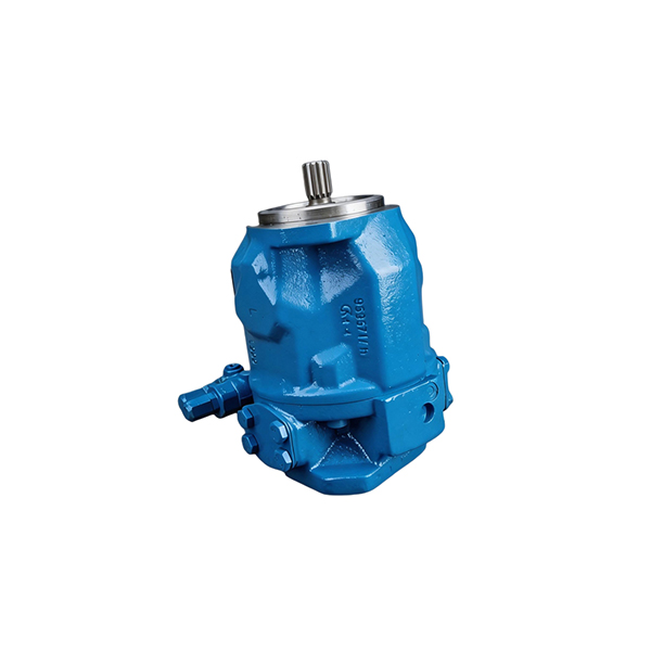
Put the old nameplate beside the actual hoses
Put the plate and control photos on the same page if the old pump has two sets of markings. The buyer can copy the readable code into the email and draw a box around the part under the oil stain. Include the last repair order if it identifies a changed control. I would keep the picture of the shaft next to the fit drawing, where the person checking the pilot and length can find it.
On a crowded drawing I would use one sheet for the power lines and a smaller sketch for the control. Take the small line that enters the pump and follow it to its other end. Where a hose goes into a valve bank, mark the section. Where it goes to a block, get that block's code. A line that leads to the reservoir may be a housing drain. Verify each label against the approved diagram with the machine owner before moving a connection.
Revision A sends the signal straight to the valve bank. Imagine today's photo shows a small block in the way. I'd put the photo on the request with the block's marking visible. The service drawing for that block can matter as much as the original plate. If nobody knows when it was added, give the supplier both drawings and a note showing the line that differs.
Write the source next to every code you send. For example, the drive drawing gives the pump shaft and pilot, the plate gives the original code, and the control-side picture shows the small ports actually installed. I would also attach the machine's operating record and put a mark at neutral and at the load that matters to the replacement. Include the speed and the date. If an old service note describes a valve or wiring change, give it a separate page. The supplier can then work through the discrepancy without treating one old drawing as the full installation.
A rotation entry is especially easy to lose on a request copied from an earlier machine. Write “viewed from shaft end” if that is the reference used on the applicable drawing and give the arrow as well. A photograph can show which end the old pump has. It takes the code and drawing to settle which way that build turns. Keep that entry with the other fit questions while the control-side quote is being checked.
If the control looks newer than the pump, find the last repair order. The nameplate may still identify the original base pump while the service record identifies the control actually fitted. Send both photographs and mark which code came from where. A guessed suffix can send the quote back to the original build even though the machine has been using another one.
Write down what should happen when nobody asks for flow
I would read the neutral state before reading the first working pressure. Find the part of the log where all the selected work sections are at rest. The gauge position goes next to each figure. A load held by another valve may have pressure left in a work line even when that line has no active signal back to the pump. Give the supplier the expected neutral state for the actual valve bank.
In a pressure-controlled circuit the important mark on the drawing is the pressure target. When the pump approaches that setting, the control can reduce displacement as demand falls. Sometimes the place setting that pressure is another device connected to the pump. A quote for pressure compensation should tell the buyer where the setting lives on the actual arrangement. Then look at neutral and ask whether the machine holds that pressure or has another unloading path.
A load-sensing sketch usually gives me two pressure marks to put next to the pump. One belongs at the outlet and the other at the signal the controller actually receives. The control has a margin it tries to maintain when it has room to move and the valve is calling for flow. At a pressure limit or the end of available stroke, the trace can stop following that simple picture. If somebody sends me the difference with no valve state, I'd send it back for the command and the pump speed at the point it was recorded.
Read the controller part of the A10VSO Series 31 data sheet alongside its ordering information. There are different pages for controls that take their direction from pressure, a remote pressure arrangement or pressure and flow. If a circuit uses a path for the signal to bleed away in neutral, find that path on the exact drawing. In a replacement quote I would ask for the page for the offered option. The document here gives an example from the Rexroth range.
Two plugs of the same shape can give the buyer a false sense of progress. Get the pinout and command range onto the drawing before signing off an electrical control. I would ask what the machine should do if that signal falls away. If it uses a hydraulic pilot instead, the equivalent question goes next to the device that sets pilot pressure. The machine maker needs the proposed behavior as well as the physical connection.

Find out which component gives the command
My note beside the narrow hose would start at the control port. I would write the name of the device at the other end. If the signal comes from more than one valve section, circle the place where they meet. If it is a wire, the same job needs the actual terminal and the device that sends the command. This makes a short question for the supplier possible when the full machine manual is unavailable.
Look for a branch before assuming the signal belongs to one cylinder. In a machine with two sections, a shuttle arrangement may send the highest requested load toward the pump. One cylinder can stop and its pressure can remain visible on a work line while the signal at the pump follows the other section. A useful note on the inquiry would give the active function and the location of the signal tap. This is also a reason to keep the valve schematic with the pump quote.
Compare a demand event at two points on the drawing
Put a cursor on the trace where the valve is open. In this example its signal channel shows 120 bar. At that cursor the outlet is at 138. The 18 bar difference goes in the column for those two taps. The cylinder's gauge, if there is one, has its own column. Ask how the proposed control should behave under that same command and oil condition. Keep the numbers as a record of a condition in the example. A setting for a real machine comes from its documentation.
At the next mark on our example plot the valve is back in neutral and the signal has fallen. Now look one line down at the outlet. If it is still up, ask what the second valve was doing. It may still be calling for pressure. The drawing can also show where the first signal goes when the spool centres. On a short log, keep the time between those changes next to the circuit that produced it.
One pressure number in an email is rarely enough. Ask for a short strip of time that shows the command before motion, while the valve is open and after release. Give the person looking at it the pump speed and oil condition. If the request is a replacement after a failure and there is no clean before-trace, say which readings come from the failed machine and which are design requirements from the machine maker. Avoid copying the readings from the failed unit into the “normal” column by default.
| Snapshot for a replacement inquiry | Put these readings on the same line | What to confirm |
|---|---|---|
| Neutral after the oil warms | Pump outlet, signal pressure if fitted, speed, valve state | Expected standby and destination of the signal |
| One function moving | Outlet, load signal, actual flow if available, command | Expected difference at the named taps and how the pump follows demand |
| Another function joins in | Outlet, signal, flow, prime mover speed and which valves are active | Whether a limit is expected or a second circuit changes the command |
| Function stops | Outlet, signal, valve state and time after the change | Where the signal goes and how quickly the pump is expected to recover |
| First cold cycle | Oil condition, initial state, speed and response under the approved test | Startup limits and whether the readings can be compared with the warm condition |
Some loggers only save maximum values. Ask for the timestamps if that is all the workshop has. A high outlet number at the start of the move and a high signal near the stop go in separate rows. To calculate a difference for one state, open both channels at the same time. Put a note beside the reading if the display reports slowly or if the original files have no common clock. This tells the reviewer what the record can settle.
The Danfoss Series 45 information is an example of the drawings and response records that can make a pump proposal easier to read. Its load-sensing circuit illustration separates system pressure, load-sense pressure, servo pressure and return. It also discusses a servo control orifice option for relevant configurations and shows why the response of one arrangement should not be assigned to another. Use the document to see what to request from the actual supplier. A published response curve belongs to its own frame, controls and test conditions.
Check the flow even if the plate and flange match
On the back of the drawing I'd write the pump rpm first. Multiply that number by the displacement in cubic centimetres per turn, then divide by 1,000 for litres per minute. That's the displacement flow. A delivery estimate takes the applicable volumetric efficiency into account. Check how far the controller can stroke the pump in the state on the drawing. If the estimate uses the nameplate maximum, mark it as an upper screening point under the stated assumptions.
Here is an example with 1,500 rpm at the pump. The actuator needs 32 L/min. At 25 cm³/rev the paper calculation gives 37.5 before losses and 33.75 with an assumed 0.90 volumetric efficiency. If a stop leaves 22 cm³/rev available in that state, the estimate comes to 29.7. The plate could still say 25. I'd put the two displacement entries in separate rows and ask which one the machine can use under load. Only one meets the flow target in this exercise.
Send the drawing with the 32 L/min requirement marked at the actuator. If a second branch was running when that number was measured, put it on the same sketch. Ask the supplier for the applicable curve and the travel limit on the offered pump. If the bench report only shows no-load delivery, file it with that label and leave the loaded row for a separate reply.
The power line on this worksheet has 32 L/min and 140 bar on it. Multiply them and divide by 600. It comes out at about 7.47 kW in the oil in the example. The shaft will have to supply more once the losses are counted. If the same prime mover is turning another load, include its demand too. There is a useful question for the drive supplier here: how much torque and power is available where the proposed pump can stroke farther than the old one?
On a machine with a reduction, draw the gearbox between the motor plate and the pump. The rpm on each side can be different. I would get the value at the pump from the installed ratio or the approved reading, then use it in the flow estimate. Take the actual running state back to the motor or drive supplier as well. A power limiting control can keep the pump below its maximum displacement in part of the range.

Use the case drain and inlet as separate installation checks
Some replacement problems appear in the first few minutes and look like controller problems. The pump may be missing an installation condition. On the drawing keep the inlet path, case drain route and pressure line separate. The reservoir sketch can show height, hose lengths and which paths share a return. Ask for the required case fill, drain routing, limits and approved startup steps for the offered unit. Take them from its current documentation and the equipment maker's procedure.
If the two small hoses disappear behind the same bracket, get the pump's port legend before deciding what goes where. Put D or the maker's actual drain designation on the housing sketch. Mark the other line at the pilot device or valve bank where it ends. A pump that now sits on its side may need the drain in a different place. The manufacturer's installation drawing can tell the installer which port to use for that orientation.
Put the old and new inlet sketches next to each other. One may have an adapter with a smaller opening under the same hose end. Write the smallest opening and the height from the oil level on the drawing. The first cold start deserves its own oil temperature beside that sketch. Ask the equipment maker how to verify the inlet condition and what to do about the oil after a failure. A warm workshop run cannot describe all those conditions.
On a stack, the spare mounting pad tells the buyer very little. Draw the second pump at the back and put its drive code beside it. What does it turn, and when does that load occur? An alternate front pump may cover the required flow and leave the back pump without the right drive. Ask for the mounting and drive drawing that covers both units together.
What a PVQ quotation needs to say
The BLINCE PVQ axial piston pump page shows a variable displacement family with several controls. Pressure compensation, load sensing, remote pressure control and electric options appear in its public technical information. That makes it useful for identifying a family to discuss. A buyer should still request the full offered code and the actual control schematic. The options on a family page do not make an old unit with a similar designation interchangeable.
The quote might say “PVQ25 with compensator.” I'd put a circle around compensator and a second one on the small hose on the old drawing. Which control is supplied, and where will that hose connect? If the drawing shows a remote valve, attach its code. Ask which pressure the remote line sets and how the pump should behave when that valve is idle. The reply can then name the code behind the short description on the quote.
Where a load-sense differential is offered as a choice, put the intended machine value on the quote and ask where it is defined and measured. A value read from a public option list is not a setup instruction. The proposed control may have a particular signal bleed arrangement, pressure limiting range or response feature. The supplier needs the circuit to say which option applies. Keep the answer with the drawing revision and include any separate valve that is part of the proposed control arrangement.
I'd put two columns on the order review. Under fit, put the shaft, flange, ports and rotation. Under behavior, put the control type, signal path, pressure limit and the neutral state. Give both columns the old and proposed drawing numbers. Suppose the flange comes back confirmed and the signal port is still missing. Send the second column back with that one blank circled. The first column can stay in the file.
| Item to confirm in writing | Useful supplier reply |
|---|---|
| Pump identity | Exact code, displacement, rotation reference and revision |
| Control behavior | Schematic or control document with the actual port legend and applicable settings |
| Neutral state | How the controller should behave with the machine's valve bank and signal condition |
| Loaded duty | Evidence for the required delivery at speed and pressure, with relevant assumptions |
| Installation | Shaft, pilot, flange, envelope, drain and inlet requirements |
| First run | Approved startup and verification documents for the proposed build |
The BLINCE hydraulic pump inquiry can take the old code, the control-side photo and the marked circuit together. In the body of the request, put the required flow and the pressure behavior the machine depends on. A note saying “last suffix unreadable” belongs right beside the photograph. The supplier can answer for the proposed control and ask about the remaining gap before quoting a particular build.
Show the supplier what the controller can still change
On the example drawing one branch has 24 L/min beside it and the other has 8. They add to 32 when both valves are in use. If the pump sheet says 34, write the pressure and speed it gives beside that line. A free-delivery figure on a bench won't answer the question about both valves under load. In the earlier calculation the limit at 22 cm³/rev left just 29.7 L/min. Ask which branch is meant to keep priority if the pump cannot deliver enough for both. The answer belongs on the valve drawing.
Suppose the cylinder is slow and the outlet has already reached its expected pressure. I'd ask for the pump control position and actual delivery first. There may be more stroke available, or the pump could already be against a limit. In the former case, the sketch gives the shop somewhere to look for the rest of the flow. In the latter case, the limit has to be compared with the flow the machine asks for at that speed.
If the first offer just gave a size and pressure, attach the signal sketch when sending it back. Leave one blank for the proposed neutral behavior. Another asks for the available flow at the loaded point. Send the page with the installed valve code as well. When only a design value exists, put the drawing revision beside it so the next person can tell where it came from.

Record what the replacement should do on the first shift
On the machine record I'd leave a space for the actual condition immediately before the first valve command. A cold start with the drive at idle may give a different pressure from warm neutral at production rpm. If the two readings came from different starts, give each one its own time and pump speed. They can both be useful to the review. Keep the running point for comparing the offered control to the normal working state.
Before the first shift, ask the equipment maker which sequence it authorizes. In the job file I would put a tab for startup and another for warm neutral. The first working movement and the return to neutral each get a mark on the original trace. When the machine was designed for concurrent motion, add the relevant point. The file gives the reviewer a place to check what the control did at each change.
A workshop may call to say the pump moves the cylinder but pressure stays high when the operator lets go. I'd ask for the plot across that instant and the drawing that shows the installed signal path. Look for where the valve bank sends the signal in neutral and whether a remote device still has a command. Any decision to change a controller or a protective function goes to the people responsible for the approved equipment procedure.
Mark the actual pump and valve bank on the plot. If both were changed on the same visit, the trace tells us how those two worked together. I would leave the original drawing in the file. Another machine may have kept the first bank, so the next reviewer needs to see which circuit the approval covers.
For the final quote review, set the circuit and the proposed part drawing next to the load sheet. The bolt pattern may already have been checked off. The question left could be as small as where the signal goes when the valve centres. Write that question under the supplier's control code and ask for the drawing that answers it. Keep the answer with the exact part being ordered.