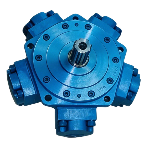

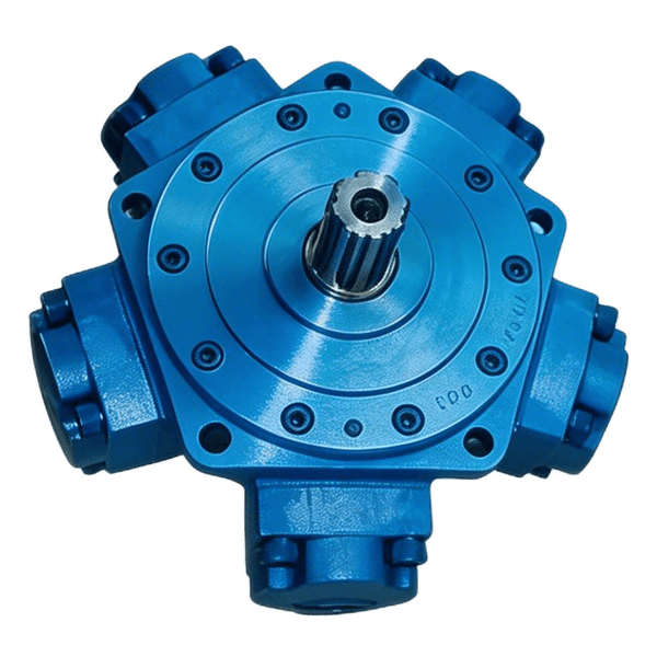
To size a radial piston hydraulic motor, first record the required shaft torque and speed, the pressure difference across the motor and the flow available under that same load. Torque sets the minimum displacement. The available flow sets how large the motor can be while still reaching the required speed. Shortlist sizes within that range, then check starting torque, continuous duty, bearing loads and the case drain for the exact model.
Start with torque and speed at the shaft you will drive
Begin with the movement the machine has to make. A wheel needs a certain speed and pull at the ground. A winch needs line speed and pull at the rope. A drum or conveyor shaft needs enough torque to start and continue turning. A motor catalogue usually asks for conditions at the motor shaft. Translate the machine requirements to that point before comparing motor sizes.
For a direct drive, the motor and driven member may share the same speed. The connection can still impose loads beyond torque, such as the radial pull from a chain or the weight and side loading of a wheel. If a gearbox sits in between, get the reduction ratio and any applicable efficiency information from the drive’s designer. A 4:1 reduction normally means the motor turns four times for one output revolution. The drive ratio allows the motor to operate at a different speed and torque. Its losses also affect the torque the motor must supply.
Record values for each distinct operating state. For example, a heavy drum may require high torque to start, then operate for long periods at a lower torque. A travel drive may need high torque at low speed on a grade and a different torque and speed on level ground. A shaft torque estimate for one state and a speed target for another do not describe a single working point. Put them on separate lines so the supplier can check both.
If the load is unknown, ask for the basis of the original model selection: an equipment drawing, a prior duty specification, a load measurement or operating data the machine builder considers reliable. A nameplate establishes the installed model when it can be identified. After a machine modification, it may no longer tell you what the drive needs. Include the size or load change when asking for a replacement. A direct replacement and an application redesign require different engineering checks.
| Duty case | What to record at the motor shaft | What it helps establish |
|---|---|---|
| Loaded start | Breakaway torque, direction, available circuit pressure and any brake release conditions | Whether the motor can begin moving under the stated load |
| Sustained duty | Running torque, target speed, duration, flow, both work-port pressures and oil condition | The operating point to compare with continuous performance data |
| Repeated transitions | Speed and load before and after the change, direction, duration and frequency | Whether a second displacement or a separate transient check is needed |
| Stop or hold | Load condition, intended action of the brake or other holding device, and circuit state | Which functions must be confirmed outside the running motor calculation |
Use a common set of units throughout the request. The examples below use N·m for torque, rpm for speed, bar for pressure difference and cm³/rev for displacement. If the machine reports MPa, multiply by 10 to obtain bar. The conversion is easy to verify and removes an avoidable source of oversized or undersized results.
Use the pressure difference the motor actually sees
Hydraulic torque comes from the pressure difference between the motor’s two work ports. During ordinary forward motoring, calculate it as the supply work-port pressure minus the return work-port pressure for the same load. If the inlet reads 240 bar and the outlet reads 20 bar at that moment, the motor sees 220 bar. A reading upstream at the pump may differ if hoses, valves or other components lie between the gauge and motor.
The outlet pressure matters on both open and closed circuits, although the system design and permitted measurement method can differ. In a shared return, another function can change the outlet pressure while the motor is running. In a closed loop, one work line can be at higher pressure and the other at charge or return-side pressure under normal operation. Use the stated flow direction and the actual pressures at the motor, then ask the machine builder to confirm which test point readings apply. Case pressure is a separate limit and is not substituted for the outlet reading in this calculation.
The same rule applies to the oil supply figure. Pump capacity can be useful when making an initial estimate. For selection, the relevant value is the flow available at the motor in the targeted operating mode, after any shared demand or upstream diversion. A pump may deliver one amount at idle and a larger amount at full engine speed. A pilot or cooling path can also alter the flow allocation. State whether flow is measured at the motor, derived from an OEM control chart or assumed for a first iteration.
For measurements, use the machine’s approved procedure and qualified personnel. A brief pressure spike may be important for protection and component limits, but it cannot be used as sustained differential pressure. A high flow reading taken before the motor comes under load cannot be paired with a pressure taken during a later stall. The useful record is a set of simultaneous values under the condition that defines the purchase.
Estimate shaft torque from displacement and pressure difference
A first running-torque estimate in N·m is pressure difference in bar times displacement in cm³/rev times mechanical efficiency, divided by 62.83. The factor follows from the unit conversion and one revolution being 2π radians. Mechanical efficiency accounts for torque losses. At 220 bar, a 1,050 cm³/rev motor with an assumed mechanical efficiency of 0.88 gives approximately 3,235 N·m. The actual result depends on the offered motor and the operating point.
The Danfoss hydraulic formula reference documents theoretical shaft torque and the relationship between motor input flow and volumetric efficiency. For preliminary sizing, use an efficiency estimate that fits the operating state if the manufacturer’s data is unavailable. Mark the assumption. A specific starting torque value or a low-speed curve from the maker gives better evidence than borrowing a running efficiency for a stopped motor.
To solve for the minimum displacement, multiply the required running torque by 62.83 and divide by pressure difference times mechanical efficiency. This gives a starting point for reviewing the catalogue. Use the required torque from the actual system design, including any explicitly chosen design allowance. There is no single allowance that fits all mobile and industrial duties. Whatever allowance applies should come from the load analysis or the equipment owner’s design criteria.
Estimate speed from the same motor’s available flow
A first speed estimate in rpm is 1,000 times flow in L/min times volumetric efficiency, divided by displacement in cm³/rev. Volumetric efficiency accounts for oil that crosses internal clearances without contributing to displacement at that operating point. It can vary with the build, pressure, temperature and speed. Keep it separate from the mechanical efficiency used in the torque calculation.
When the desired speed is fixed and the circuit has a known flow limit, rearrange the equation. The maximum displacement in cm³/rev is 1,000 times available flow in L/min times assumed volumetric efficiency, divided by required rpm. If the candidate’s displacement exceeds this upper limit, the circuit cannot reach the speed in the assumed operating state. The manufacturer’s verified curves are needed for final confirmation, particularly at low speed or other points where efficiency changes.
A larger displacement usually produces more theoretical torque at a given differential pressure and turns more slowly at a given flow. Those comparisons assume the other quantities are held fixed. In a real machine, the pressure responds to the load and circuit. Reviewing the torque and speed limits together is more useful than expecting the system pressure to drop a predetermined amount when you choose a larger motor.
Compare three sizes at one working point
Suppose a hypothetical direct drive must deliver 3,200 N·m continuously at 55 rpm. The motor inlet is 240 bar under that load and the outlet is 20 bar. Available flow at the motor is 70 L/min. For the first comparison, assume 0.88 mechanical efficiency and 0.90 volumetric efficiency at this point. The figures are illustrative. They are neither product ratings nor measurements from a BLINCE installation.
The torque calculation gives a minimum displacement of 3,200 × 62.83 ÷ (220 × 0.88), or about 1,039 cm³/rev. The speed calculation gives a maximum displacement of 1,000 × 70 × 0.90 ÷ 55, or about 1,145 cm³/rev. The preliminary window runs from 1,039 to 1,145 cm³/rev under the stated assumptions. Now check candidate sizes against both conditions.
| Hypothetical displacement | Estimated running torque at 220 bar | Estimated speed at 70 L/min | Flow needed for 55 rpm | First outcome |
|---|---|---|---|---|
| 900 cm³/rev | About 2,773 N·m | 70 rpm | 55.0 L/min | Fits the flow limit and falls short on torque |
| 1,050 cm³/rev | About 3,235 N·m | 60 rpm | 64.2 L/min | Clears both preliminary requirements |
| 1,250 cm³/rev | About 3,852 N·m | 50.4 rpm | 76.4 L/min | Clears torque and exceeds available flow for the target speed |
The 1,050 cm³/rev line deserves a datasheet check. At the assumptions used, it is only about 35 N·m above the stated running requirement. A modest change in efficiency, return pressure or actual load could use up that margin. Treat the result as a candidate, then request documented performance and any design margin the application requires. The 60 rpm figure is the estimate at the full flow available. It is not the intended setpoint if the machine is regulated to run at 55 rpm.
Recheck the candidate when outlet pressure rises
Suppose the motor inlet stays at 240 bar while outlet pressure rises from 20 to 40 bar during an overlapping function. Keep the 55 rpm target, 70 L/min available flow and efficiency assumptions unchanged for this comparison. The pressure difference falls to 200 bar. The minimum displacement rises to about 1,142 cm³/rev. With 70 L/min available, the speed-based maximum remains about 1,145 cm³/rev. That leaves a very narrow mathematical window. Request actual pressure and flow records for the overlapping function before relying on it.
If outlet pressure rises to 50 bar with the same inlet pressure, the differential is 190 bar. The minimum displacement becomes 1,203 cm³/rev when rounded up to a whole cubic centimetre per revolution. It exceeds the speed-based maximum of about 1,145 cm³/rev. In this case, selecting a larger displacement to meet torque would lower the achievable speed under the assumed supply. The system team can review the confirmed load, flow availability, allowable circuit pressure, target speed and drive ratio. The worksheet identifies what has to change before the supplier can select a motor confidently.
The example also gives a useful power check. At 3,200 N·m and 55 rpm the shaft needs approximately 18.4 kW. At 220 bar and the hypothetical 64.2 L/min required by the 1,050 cm³/rev candidate, hydraulic power at the motor would be about 23.5 kW. These figures describe the motor boundary at one point. The prime mover has to cover additional system losses, and its approved capacity should be checked separately.

Check startup, continuous running and any second displacement
Treat start as a separate point whenever the machine moves from rest under load. Loaded start can involve static friction, tight material, a grade, a brake release sequence or a changing pressure supply. Ask the supplier for starting torque for the offered model or a selection curve that covers that condition. A nominal running torque value does not state what the shaft can develop from rest. If a legacy assembly has a brake, request documentation of the exact brake and its release conditions.
For sustained duty, ask for the motor rating at the actual speed, pressure difference, flow and oil condition. Check continuous limits and any restrictions that apply to their combination. Product families can have maximum figures for pressure, speed or torque that belong to different duty points. Review an operating envelope or a selection report for the speed and torque pair. Where the application spends long periods at low rpm, ask about smoothness and available torque in that region as well as the highest allowed speed.
If the current machine has two displacement modes, list both. A travel drive may use one setting for higher torque and another to reach a higher speed. Get the actual displacement values, pressure and flow available in each mode, how the shift is commanded, and which control signal the machine provides. A second displacement figure alone does not establish that the replacement responds correctly to the original valve or controller.
The demand during a shift also deserves its own record if the machine changes mode under load. Ask at what conditions a shift is permitted and what changes in return, charge or case conditions must be considered. The hydraulic circuit should support the required transition without relying on an unverified assumption about internal controls. Procurement can put the controller or valve details on the same request as the two duty points, helping the vendor identify the correct build.
For an intermittently loaded drive, state the load magnitude, duration and recurrence. A load for several seconds once per cycle is different from the same load repeated every few seconds for an entire shift. Check the details against the manufacturer's duty definition, rather than putting all short events in a single “peak” column. Include the hottest and coldest oil conditions seen during the relevant operation so the engineering review can use applicable viscosity information.
Confirm the shaft, bearings and support arrangement
Torque is only one kind of load on the output connection. Radial load acts across the shaft. Axial load acts along its axis. Wheel weight, belt or chain tension, and the location of a sprocket or wheel face can change the bearing load. Two machines can ask for the same driving torque and need different bearing configurations. Show where each external force acts in relation to the reference on the motor drawing.
The Poclain MS18 and MSE18 technical catalogue provides a primary example of how a manufacturer plots permissible radial load and bearing service life against the force’s applied position. Its curves state the relevant configurations and conditions, including treatment of axial load. Use the method to prepare your request and the offered motor’s own curves to judge the actual load. Those published limits belong to the Poclain configurations shown in its catalogue.
For example, a drive drawing might place a chain force 80 mm from the supplier’s stated reference plane. If an adapter or hub moves the sprocket outward to 110 mm, the load application point has changed by 30 mm even if the chain pull stays the same. For a simplified transverse load of 5 kN, the corresponding moment about that reference goes from 400 to 550 N·m. Use this simple moment calculation to explain the change to the supplier. Confirm the actual allowable radial and axial load combination and bearing life against the mounting configuration and the offered motor’s data.
Ask whether the assembly carries an external load directly or drives a separately supported shaft through a coupling. In the second case, identify which support actually takes the load and what the coupling transmits. A shaft that drives a supported conveyor can have a different set of loads from a direct sprocket mounted on the motor. Include the relevant side view and the intended support arrangement. Select the bearing version on the drawing rather than treating all motors with one displacement as mechanically equal.
On replacement work, compare the pilot, flange, bolt pattern, shaft or wheel mounting, engagement, port orientation and installed envelope. Inspect the assembly drawing for a retaining fastener or axial location that a front-view photo may miss. Record the tolerances or reference dimensions when available. If the proposed part needs a spacer or adapter, ask the vendor to show how the assembly changes. Oil lines and sensors also need access after the motor is installed.
| Mechanical condition | What to put on the drawing |
|---|---|
| Direct wheel or sprocket | Force direction, point of application from a named reference, speed and load state |
| Belt drive | Pulley position and the relevant loads or tension information from the drive design |
| Supported coupling | Location of both supports, coupling type and applicable alignment or axial movement limits |
| Replacement with adapter | Both mounting faces, installed thickness, changed offsets and any clearance constraints |
| Combined radial and axial load | Expected magnitudes, directions and which loads occur together |
Verify the case drain, ports and circuit features
The case drain, where specified, routes oil from the motor housing. It has its own flow, pressure and plumbing limits. Compare the manufacturer’s diagram and case pressure limit with the machine’s route at the proposed operating conditions. A hose ending at the tank can still have pressure loss on the way, particularly if it passes through shared components. Check the fitting positions, available space and connections using the drawing of the exact motor and the OEM circuit.
Inlet and outlet positions affect how the motor fits the machine and which direction it turns. For a reversible drive, show both required operating directions and the viewpoint used to describe clockwise rotation. A third connection can have a different role on another motor. Locate drains, pilot connections, shift ports and brake release ports by the approved diagram. Put their pressure and flow conditions on the request when they are known.
For a closed-loop application, ask for the relevant charge, flushing or replenishment requirements of the exact design, and for any permitted case-to-work-port pressure relationship. For an open circuit, describe the return path, any back pressure present under load, and whether another function shares it. Cooling and oil cleanliness should follow the machine and motor documentation. Include the fluid type and temperature range so the vendor can check the appropriate seals and viscosity conditions.
If a supplier proposes a different motor from the one originally installed, request a drawing and operating schematic tied to the quote. The drawing should identify all port functions and their orientation. A similar product family or cross-reference is useful for finding a candidate, while the purchase still needs the configuration and duty checks. A confirmed substitute addresses fit, direction, controls, working point and load together.
Request a specific selection rather than a family maximum
A useful preliminary request can begin with a one-page table. Add the machine model, main function and proposed mounting sketch. Provide expected shaft torque and speed for sustained use, plus the startup requirement if it governs. State the pressure readings and flow available at each condition. If pressure or flow is estimated, say where it came from so the supplier can identify which input needs confirmation first.
Use the BLINCE radial piston motor range for category discovery. The LD series radial piston motor is one family for which a drawing review may be appropriate. Ask for the proposed model and variant, with the relevant curves and outline drawing. Product-category filters and family descriptions cannot establish the operating limit of an unspecified build.
| What you send | What you ask the supplier to confirm |
|---|---|
| Machine function and the load or source drawing | The exact motor’s configuration code and place in the drive |
| Running torque and speed with available flow and both work-port pressures | Continuous operating point and the basis of the selection |
| Start torque, stopping conditions and any brake or speed change | Published limits and relevant control or holding features |
| Mounting drawing, shaft loads and application positions | Exact mounting, shaft, bearing configuration and applicability of load data |
| Fluid and temperature range, main ports and drain route | Limits and connections for the offered configuration |
| Items the buyer cannot yet confirm | The next required drawing, measurement or test |
Ask the quoted supplier to identify the data used to make the selection and the conditions that remain unconfirmed. When two candidates meet the initial torque and speed figures, compare their published operating envelopes, bearing requirements and control needs before comparing price. Record any changes to the bearing support, required flow at target speed and control plumbing beside the relevant order code.
Agree on how the installation will be checked before releasing a purchase order. For an OEM project, the reviewer may want a sample or a documented test at the agreed operating point. For a service replacement, a verified drawing and the machine’s prescribed acceptance procedure may be more relevant. If startup, duty or fit cannot be verified in the first review, leave that decision open and state what will close it. This is more actionable than a quote that lists only displacement and one peak pressure.
Questions buyers ask about radial piston motor sizing
What pressure should I use to calculate hydraulic motor torque?
Use the difference between the two working-port pressures at the motor in the target motoring condition. A pump outlet reading alone may miss supply losses or return pressure. Include the mechanical efficiency basis and check the result against the offered motor’s data for that speed and duty.
Why can a larger radial piston motor meet torque but miss speed?
For a given available motor flow, increasing displacement reduces theoretical speed. Larger displacement can provide more torque at the same differential pressure, but the flow needed for a specified speed rises. Calculate both limits from the same duty point and verify the candidate against its actual performance data.
What should I send for a replacement motor inquiry?
Send the complete old model code, a mounting and shaft drawing or marked photos, port and drain information, and the required torque and speed. Add the available flow and working-port pressures. If the old unit has a brake, shift function or a load directly on the output, include those details so the supplier can review the actual configuration.
To request a BLINCE radial piston motor review, describe the application, the exact point the motor has to deliver, and which original components must stay on the machine. Include the load sketch and identify the inputs that still need confirmation. Ask for a proposed model with its documented torque, speed, fit and circuit requirements at the stated duty.