
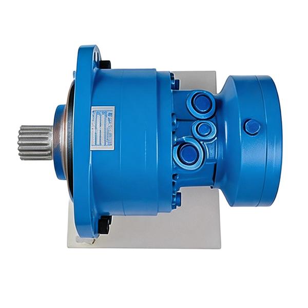
A low-speed, high-torque hydraulic wheel motor can carry a wheel only if the specific shaft, bearings and flange are approved for the loads at the actual wheel offset. A spacer can raise the bending load even when the machine weighs exactly the same. If the chosen motor lacks a load chart or written approval for the proposed assembly, compare a hub with its own bearings. You can keep one-to-one direct drive with that layout.
A motor-mounted wheel can give an industrial carrier or grounds machine a compact drive with few parts outside the motor. Its displacement and torque curves tell you what it can deliver hydraulically. A bearing load chart answers a different question. Use the figures for the wheel and machine to make the mechanical check before concluding that a motor with the right speed and torque can also support the hub.
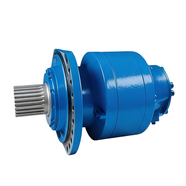
Trace the wheel loads from the tire to the chassis
A tire pushes and pulls on the ground. The ground reaction travels through the wheel and hub into the chassis. In a wheel-on-motor arrangement, the shaft and motor bearings carry those reactions before the housing and its flange transfer them to the frame. When a wheel has its own supported hub, the hub bearings and axle housing carry the main wheel reactions. The motor transmits torque through a coupling or drive suited to the arrangement. Either design can be one-to-one direct drive, with the wheel and motor turning at the same speed.
A third layout uses reduction gearing or a chain drive. The motor turns faster than the wheel and the reduction increases available wheel torque for a given motor torque. The gearbox or supported axle still needs to carry the wheel loads that reach it. In a chain-drive design, chain tension can impose its own radial load on the motor shaft if the sprocket is mounted there. Draw the path of each force through the assembly, including the path for torque. That exercise often resolves an ambiguity the phrase “direct drive” leaves open on a purchase order.
| Drive layout | What turns the wheel | Where tire forces are carried | Evidence to request |
|---|---|---|---|
| Wheel on motor shaft | Motor shaft and wheel hub at the same speed | Motor shaft, bearings, mounting flange and frame | Exact configuration, shaft load curve, hub drawing and required life |
| Direct drive with independent hub | Aligned coupling between motor and supported hub at the same speed | Hub bearings, axle structure and frame | Coupling rating and alignment limits alongside the hub load and life data |
| Drive with reduction | Gear or chain transmits torque at a ratio | Supported hub, axle or rated gearbox, with any input side load checked separately | Reduction, efficiency, speed range, load limits and brake locations |
Start with a simple cross-section. Mark the motor mounting face, wheel center plane, hub engagement length, and where the load acts. A mounting face is the surface the manufacturer uses as a reference on the drawing. Read the diagram legend before selecting a datum. The wheel’s advertised offset may be measured from its own hub mounting surface, which can be some distance from the motor’s reference face. A drawing with those faces identified is more useful than a single offset number in a message.
Use the planned wheel, hub and spacer dimensions. On a replacement, photograph the assembly square to the shaft and note any differences from the machine drawing. Changes in wheel width, tire size or hub geometry can shift the load line. A recessed wheel flange can bring the load closer to the bearings on some motor designs, while an adapter can move it out again. The Danfoss general orbital motor technical information uses wheel-motor cross-sections to illustrate how a recessed flange changes where a hub can sit.
Get the forces for the most heavily loaded wheel
Start with the load on one driven wheel in the condition you care about. Dividing the machine weight by its wheel count is a rough estimate for a stationary, balanced machine on level ground. A load over one end, a lifted or lowered attachment, a turn, a ramp, or a wheel on an obstacle can put more demand on a particular position. For an existing machine, individual wheel weights under the representative equipment and payload are more informative than total mass alone. For a new build, get the load cases from the chassis team, including the assumptions about load transfer and terrain.
Wheel forces have directions. Vertical reaction supports the machine. Longitudinal force acts in the direction of travel during drive or braking. On a typical straight axle these components are perpendicular to the shaft and contribute to radial load, which means force across the shaft. Cornering or side slope can add an axial force, which acts along the shaft. Offset forces can also create an overturning moment. The allowable way to combine these loads depends on the bearing assembly and how the manufacturer defines its rating.
Before asking for bearing life, distinguish the conditions you need checked. Frequent level travel sets one duty. Repeatedly turning with extra payload, hitting a floor joint, or operating with one wheel on a small ramp creates other cases. For wear and life, supply approximate operating hours, speed and how often each condition occurs. For maximum force, report known shock and lateral events separately. A short impact may matter more to the maximum permitted load than to a simple time-average reading.
| Wheel data | Useful way to report it | Where it helps |
|---|---|---|
| Maximum vertical reaction | Newtons per driven wheel and the machine position where it occurs | Load distribution and radial capacity |
| Longitudinal reaction | Drive and braking force per wheel at the representative duty points | Traction torque and radial loading |
| Lateral reaction | Direction, force and duty, including side slope or turning | Axial loading and overturning effects |
| Effective loaded tire radius | Metres from axle centre to contact line for torque screening | Converts traction force to torque and travel speed to rpm |
| Hub and wheel position | Section drawing from the manufacturer’s datum to the assigned load line | Determines chart position and moment arm |
| Shock and duty cycle | Peak events, frequency, duration, travel speed and loaded operating hours | Separates peak capacity from repeated-load service life |
See how a spacer changes the shaft check
Consider a simplified straight-travel case with 3.0 kN of vertical reaction and 1.2 kN of longitudinal traction on one wheel. For this first pass, assume the two components are perpendicular to each other and both act perpendicular to the axle. The radial force magnitude is the square root of the sum of their squares: √(3.0² + 1.2²), or about 3.23 kN. At a loaded tire radius of 0.25 m, the 1.2 kN tractive force implies about 300 N·m of traction torque at the wheel. This is a single illustrative wheel under an assumed load. Turning, slope, braking and obstacles require their own cases.
Suppose the radial load line sits 70 mm from the motor mounting face in the first layout. Its simple moment about that face is 3,230 N × 0.070 m, or about 226 N·m. Moving the line to 110 mm gives about 355 N·m. The spacer leaves the 3.23 kN radial force unchanged in this example. It increases the simple moment about the mounting face by about 57%. That bending moment is distinct from the 300 N·m that turns the shaft. The rated load must now be looked up at the new chart distance, using the correct flange and shaft.
| Illustrative wheel on motor shaft | First layout | With load line farther out |
|---|---|---|
| Wheel load line from motor datum | 70 mm | 110 mm |
| Radial load in the example | 3.23 kN | 3.23 kN |
| Approximate moment at the mounting face | 226 N·m | 355 N·m |
| Traction torque at the assumed tire radius | 300 N·m | 300 N·m |
This is a comparison of two lever arms. It does not calculate the force in each bearing or account for the contact patch’s lateral offset, actual bearing spacing or axial force. Treat it as a way to flag a change that the supplier must check on the drawing. With a supported hub, repeat the geometry check at the hub’s own bearing positions and confirm what residual load is allowed through the coupling. Moving the load away from the motor changes where the force is carried, so the responsibility for validating that load moves as well.
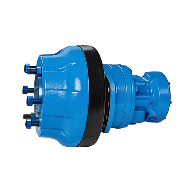
Read the bearing chart for the shaft and flange you would buy
Get the complete motor configuration, including the shaft and mount options. Locate the drawing that accompanies the load chart. Identify the positive and negative directions, the unit for distance, and the reference face for the configuration you intend to order. A motor maker may publish different curves for wheel, standard flange and brake arrangements. The Danfoss OMT and OMV technical manual shows separate shaft loading diagrams for several mount arrangements. The drawings show why series names alone are too broad for this check.
Read the chart at the proposed load position. Verify whether the line represents a maximum shaft load or a load tied to bearing life under stated conditions. The Danfoss OMT and OMV manual, for example, gives separate maximum and life-based curves. Its life reference specifies 100 rpm, rated output torque and zero axial force, among other conditions. A configuration can clear a peak load limit and still fall short of the hours needed for repeated travel duty. Ask for the corresponding limits for the exact part on your quote.
Suppose the example wheel also sees a 0.6 kN lateral reaction in a turn. The radial load chart’s zero-axial-force assumption no longer describes that load case. Give the supplier the direction and point of application of the lateral force together with the vertical reaction, traction, offset and speed in that turn. The drawing should show the tire contact patch relative to the axle as well as the wheel center plane so the reviewer can account for overturning effects.
Ask the supplier how the radial curve applies when the wheel also produces axial thrust. Lateral force is often largest during turning or when the vehicle crosses a slope. It can arrive while vertical load and traction are already present. Describe whether it changes direction in service. If the catalog gives separate radial and axial values, ask how they combine and whether rotation direction or a brake arrangement changes any limit. A machine with repeated impacts also needs the supplier’s interpretation of transient loads and the customer’s required service life.
Confirm the wheel interface on an assembly drawing
Mark the hub’s shaft profile, diameter, engagement length and retention arrangement on the assembly drawing. A matching nominal spline count can still leave questions about tooth form, fit and engaged length. For a tapered shaft, the taper and seating position matter as much as the nominal diameter. The motor drawing and wheel-hub drawing should agree on where the wheel actually sits. Show bolt patterns, centring features and clearance to the frame, including the space needed to install fittings and service the unit.
Where the motor is separately coupled, use the hub or axle drawing to prove that tightening the coupling and installing the wheel leaves the expected alignment and axial freedom. Provide likely frame deflection or misalignment if the machine builder has calculated it. For a geared hub, ask who rates the input coupling, output bearings and reduction assembly. A flange that bolts to the frame offers little information about what the case, joint or bearings will carry in service.
Inspect replacement evidence with the same split in mind. Oil at the shaft seal, a fretted hub or damage at the mounting bolts deserves a mechanical and hydraulic review, especially if the machine changed tires, wheel offset or payload. The old unit’s part number helps recover its starting specification. Document any changes in the operating geometry before asking for a nominal equivalent. A matching motor may inherit the previous installation’s loading if the mounting error or wheel change stays in place.
Compare speed and torque after choosing the wheel layout
Use effective tire radius and the required travel speed to calculate wheel rpm. At a nominal rolling speed of 6 km/h, or about 1.67 m/s, and 0.25 m effective radius, wheel speed is about 63.7 rpm. The estimate is travel speed × 60 ÷ (2 × π × loaded tire radius). Tire slip and differences between static and dynamic rolling radius can change actual ground speed, particularly on loose terrain. If ground speed is important for the machine, confirm the effective rolling radius for that calculation and the loaded geometry used for force estimates.
For the 300 N·m wheel torque in the example, a one-to-one motor needs about 300 N·m at the shaft before allowing for mechanical transmission losses. If a 3:1 reducer were used, with an assumed 90% mechanical efficiency at the point, motor speed becomes about 191 rpm and required motor torque is about 111 N·m. The powered wheel still sees its original traction and support loads. The mechanism that carries them can now be selected separately. The 90% is a planning assumption to be replaced with reducer data for the duty.
The gearing comparison helps you ask for an appropriate curve. A motor that supplies the necessary wheel torque directly may be happiest above the expected crawl speed. A reduced drive can move the motor into a more practical speed band and can use a lower-torque motor. It also adds parts, transmission losses, and potentially backlash. At fast travel, the same ratio can take the motor or gearbox beyond an operating limit. Verify starting torque, minimum usable speed under load, normal travel speed, and the maximum speed at the upper flow condition.
Tell the supplier which conditions happen together. Required torque to start on a slope occurs near zero speed, while high speed may occur on level travel at reduced torque. Ask for an operating range or measured points that reflect those events. Use the working pressure difference from the motor’s inlet to outlet for the hydraulic torque check, rather than a pump relief setting or inlet reading alone. Available flow belongs at the motor or drive branch, particularly in circuits with multiple wheels, steering priorities or bypass flow. The broader BLINCE guide to orbital motor applications helps compare motor types if the architecture is still open.
Separate starting, travel and braking in the quote
For starting, give the loaded machine position and the required tractive force. A large torque estimate has limited value if the tires cannot transmit that force under the specified ground conditions. Give the supplier the normal moving torque as well as the breakaway case. In a multi-wheel arrangement, describe how flow and torque are divided, including any differences between wheels in a turn or on uneven ground. The hydraulic designer should review how the circuit behaves when one wheel loses grip.
During travel, ask for the permitted pressure and speed combination over the duty cycle. The motor may see a different backpressure in reverse or during deceleration. If the proposed unit needs a case drain, a line that carries internal leakage away from the housing, confirm the approved routing and pressure with the maker. The return path and the case pressure limits can affect seal operation and the suitability of a replacement with a different drain arrangement.
For a machine travelling downhill or decelerating, the wheel can drive the motor. Describe the overrun and stopping cases in the inquiry. Ask the machine designer to specify service braking, parking and safe behavior after loss of hydraulic power. A motor sized for propulsion establishes neither a parking rating nor a complete downhill control design. If a reduction is involved, brake placement affects the torque the brake must handle and whether a failure can disconnect it from the wheel. Confirm who checks the complete vehicle system under the applicable requirements before relying on any individual component rating.
Request written confirmation of the wheel load
Start with the machine type and one sentence about the problem. For example, “We want to keep one-to-one drive at each wheel and compare a motor-supported hub with a separately supported hub.” Give the exact old motor code on a replacement, with photos showing the wheel, flange and shaft connection. Include whether the current part carries the wheel directly. This detail tells a supplier whether an apparently matching orbital motor needs its bearings evaluated as a wheel support.
Send a drawing section and a small table of load cases. The drawing shows load distance from the stated datum, the hub interface, and the tires used. The table gives per-wheel vertical, longitudinal and axial loads, estimated peak events, expected life, wheel rpm and torque for each relevant condition. Add the pump or motor-branch flow, motor inlet and return pressure where known, oil and temperature, and the brake and drain arrangements. Mark calculated quantities and those awaiting measurement so the supplier can respond with the right data.
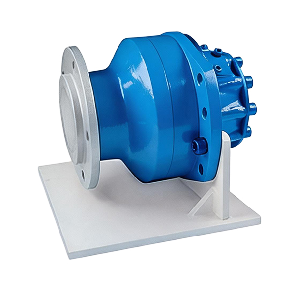
For an orbital option, review the BLINCE OMT series motor or the BLINCE OMV series motor as candidate families. The OMT page specifically asks for radial force and its distance from the mounting face when there is an external load, and the OMV page lists wheel drives among its applications. Ask which exact configuration is offered and request its load diagram with the proposed shaft, flange and duty identified. If a quote gives only displacement, pressure and hydraulic torque, it still needs the wheel support information for a shaft-mounted proposal.
| Quote output | Detail worth getting in writing |
|---|---|
| Motor and mounting configuration | Full model, flange, shaft, port and drain details, with a drawing revision |
| Mechanical load review | Radial and axial values at the actual load line with stated speed, shock and life conditions |
| Hydraulic operating points | Torque and speed for start, crawl, normal travel and peak flow, with pressure and fluid conditions |
| Hub or reduction assembly | Interface, coupling or ratio, usable load ratings and chosen responsibility for support |
| System considerations | The machine builder’s responsibilities for braking, parking, structural mounts and final validation |
Where a motor-supported wheel lacks written load confirmation, leave that option open for a component review or request a supported-hub alternative. If a larger motor is proposed, compare the actual bearing evidence and mounting geometry before accepting it. A larger displacement will change speed and torque for the same oil supply, while its mechanical fit depends on the hardware selected. For a configuration review, send BLINCE Hydraulic the wheel drawing and load cases so the motor and proposed load path can be discussed on the same request.
Common questions about hydraulic wheel motor selection
Can I mount a wheel straight on any low-speed hydraulic motor?
Use direct shaft mounting only when the exact motor and approved hub arrangement carry the forces and moments at the actual offset and duty. Verify the radial and axial checks, peak force and required life. A separately supported hub can still give direct, one-to-one drive if the chosen layout calls for it.
Does high starting torque mean the bearings can carry more vehicle weight?
Starting torque describes the motor’s ability to turn the shaft at the stated hydraulic conditions. Bearing and shaft loading concern the forces introduced by the wheel and the positions where they act. Request both ratings for the exact configuration so each can be compared with its own load case.
Can I use the tire’s advertised diameter for the drive calculation?
It is suitable for an early estimate when measured values are unavailable. Use loaded geometry for the mechanical drawing and effective rolling radius for speed calculations where accuracy matters. Look again at the offset and load if the tire package changes, especially when a spacer moves the wheel outside the original position.
When should I ask for a separate hub or a reducer?
Ask about a separately supported hub when the motor lacks suitable load approval or when the wheel’s force and offset exceed its limits. Consider a reducer when direct motor rpm and torque cannot fit the vehicle’s duty or the required low-speed behavior. Then verify the supports, ratio, coupling, braking and both ends of the usable speed range. The preferred layout should come with a load path and drawings your machine builder can check.